Circuit Skills: Surface Mount Devices
Summary
TLDRThis video introduces viewers to surface-mount devices (SMD) in electronics, highlighting their prevalence in modern circuits. The presenter discusses various SMD sizes, their applications, and the tools needed to solder these tiny components, such as fine tweezers, a soldering iron, and magnifiers. A hands-on project is demonstrated, building a light-controlled oscillator with a 555 timer in an SMD package. Through the project, viewers learn to solder components on an SMD prototyping board. The video encourages beginners to get started with SMD soldering using an experimenter's kit for easier learning and practical experience.
Takeaways
- 😀 The video emphasizes the shift from through-hole components to surface mount devices (SMD) in modern electronics.
- 😀 Surface mount devices (SMD) are smaller components soldered directly onto the surface of a PCB, unlike through-hole components which have leads that go through the board.
- 😀 The common SMD sizes for resistors and capacitors are 1206, 0805, and 063, with even smaller sizes like 0402 available.
- 😀 SMD components are designed for machine handling, making them smaller and more compact, which is useful for devices like cell phones.
- 😀 The presenter mentions that while working with SMD components might seem daunting due to their size, it’s possible to solder them with the right tools and techniques.
- 😀 For beginners, it’s suggested to start with larger SMD components (e.g., 1206 size) to build familiarity before tackling smaller sizes.
- 😀 The presenter demonstrates how to solder SMD components on a small prototyping board using a variety of tools like fine tweezers, solder wick, and magnifying loops.
- 😀 The use of adhesive putty (such as FunTac) is recommended to hold components in place during soldering to prevent them from sliding around.
- 😀 The presenter uses 0.32 diameter solder, though smaller diameter solder (0.15) would make soldering easier for these tiny components.
- 😀 A small through-hole photo cell was adapted for the project since SMD photo cells weren’t available, showing that through-hole components can sometimes substitute SMD parts.
Q & A
What is the primary difference between through-hole components and surface-mount components?
-Through-hole components have leads that go through holes in a PCB and are soldered on the other side, while surface-mount components are soldered directly to the surface of the PCB, making them more compact and suitable for modern electronics.
What does the term 'SMD' stand for, and what does it refer to?
-SMD stands for Surface-Mount Device, which refers to electronic components designed for mounting directly on the surface of a PCB, unlike traditional through-hole components.
Why is it important to get familiar with surface-mount technology (SMT)?
-It's essential to understand SMT because many newer electronic designs, such as chips for smartphones, are only available in surface-mount packages, making them crucial for working with the latest technology.
What are the standard sizes of SMD resistors and capacitors?
-The standard sizes for SMD resistors and capacitors are 1206, 0805, and 063. There are also smaller sizes, such as the 0402 package, which is very tiny.
Can you solder small SMD components yourself, even though they are tiny?
-Yes, it is possible to solder small SMD components. While it may seem daunting, tools like tweezers, magnifying loops, and appropriate soldering techniques can make it manageable.
What is the size of the SMD packages the presenter chose to start with, and why?
-The presenter chose to start with the relatively large 1206 size for SMD components to make it easier to handle and solder as a beginner.
What tools were used by the presenter for soldering the SMD components?
-The presenter used fine-tipped tweezers, solder wick, a magnifier loop, 28 gauge wire, and adhesive poster putty (also known as FunTac or BlueTac) to hold the components in place while soldering.
What challenge did the presenter face with the adhesive putty, and how was it addressed?
-The presenter was concerned that the adhesive putty might elevate the SMD components too much from the board. However, they found that it did not cause any issues, and the chip stayed in place while soldering.
What alternative did the presenter use when they couldn't find surface-mount photo cells?
-The presenter adapted a small through-hole photo cell for the project instead of using a surface-mount version.
How did the presenter test the circuit after assembly?
-The presenter connected a 9V battery to the circuit to power it up, but there was no power switch, so the circuit turned on as soon as the battery was connected. The presenter did not initially know whether it would work, but it functioned as intended.
What is one possible improvement the presenter mentioned for the power source of the circuit?
-The presenter suggested replacing the 9V battery with a smaller power source, such as a coin cell, to make the circuit more compact.
Where can someone find a kit to start experimenting with surface-mount technology?
-The presenter recommended checking out the SMD Experimentor Kit available at jamco.com for those interested in starting to work with surface-mount circuitry.
Outlines

Esta sección está disponible solo para usuarios con suscripción. Por favor, mejora tu plan para acceder a esta parte.
Mejorar ahoraMindmap

Esta sección está disponible solo para usuarios con suscripción. Por favor, mejora tu plan para acceder a esta parte.
Mejorar ahoraKeywords

Esta sección está disponible solo para usuarios con suscripción. Por favor, mejora tu plan para acceder a esta parte.
Mejorar ahoraHighlights

Esta sección está disponible solo para usuarios con suscripción. Por favor, mejora tu plan para acceder a esta parte.
Mejorar ahoraTranscripts

Esta sección está disponible solo para usuarios con suscripción. Por favor, mejora tu plan para acceder a esta parte.
Mejorar ahoraVer Más Videos Relacionados
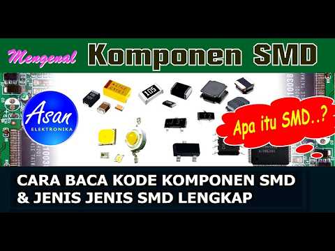
Belajar Komponen SMD, Apa itu THT & SMT juga SMD?, Mengenal komponen SMD

Elektronika Dasar 004 Resistor 04 Universitas Jember
Lec 63: Familiarity with Components - I

Pahami Dasar Elektronika Digital
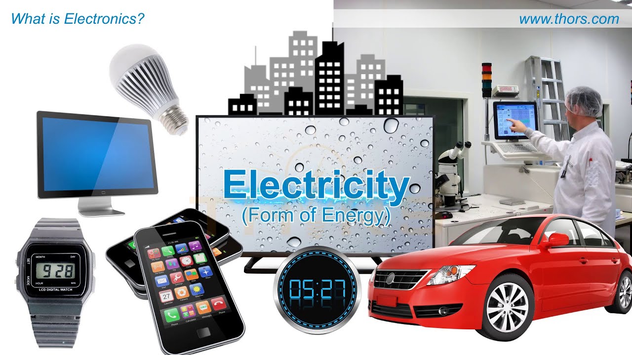
What is Electronics? || Electronics Terminology Course Preview
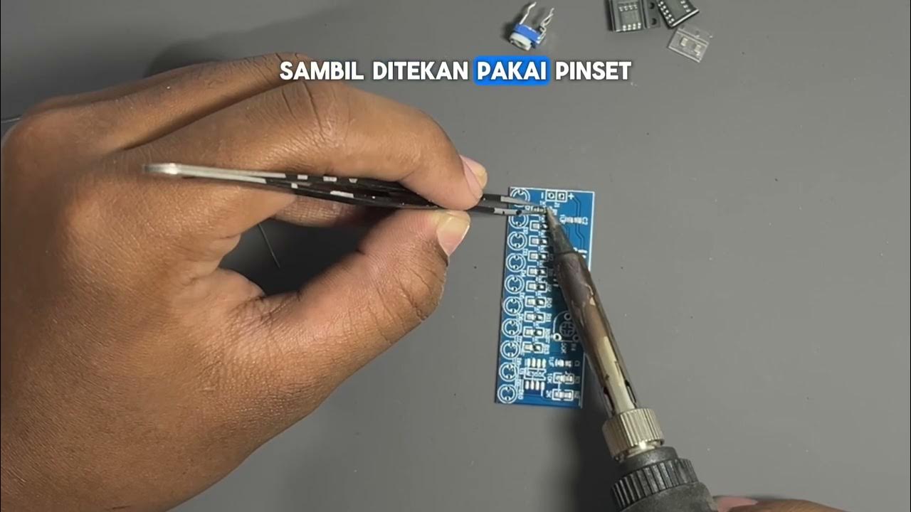
Cara Menyolder SMD Menggunakan Solder Biasa Tanpa Mesin
5.0 / 5 (0 votes)
