How to convert AC to DC | 3D Animation
Summary
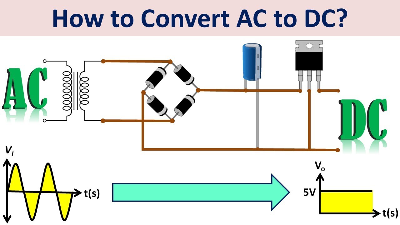
TLDRThis educational video explains the process of converting 230V AC to 12V DC, essential for powering modern electronic devices. It outlines four key steps: using a step-down transformer, rectification with diodes to change AC to DC, smoothing the pulsating DC with a filter circuit, and finally regulating the DC voltage with an IC for a stable output. The video covers both half-wave and full-wave rectifiers, emphasizing the efficiency of full-wave rectification.
Takeaways
- 🔌 There are two main types of current: AC (Alternating Current) which reverses direction periodically, and DC (Direct Current) which flows in one direction.
- 🏠 Homes typically receive AC power from the grid, but most modern electronic devices require DC power, necessitating a conversion process.
- 🔄 The conversion of AC to DC is known as rectification, and this video focuses on converting 230V AC to 12V DC using a traditional transformer-based design.
- 🔩 The process involves four main steps: stepping down voltage levels, converting AC to DC, obtaining pure DC from pulsating DC, and regulating the DC voltage.
- ⏬ A step-down transformer is used to reduce the 230V AC to a lower voltage suitable for further conversion to DC.
- ⚡ Rectification is achieved using diodes, which allow current to flow in only one direction, thus converting AC to DC.
- 🔄 Half-wave rectifiers pass only half of the input wave, while full-wave rectifiers use both halves of the AC waveform for more efficient conversion.
- 💡 Full-wave rectifiers can be implemented using either a center-tapped transformer with two diodes or a bridge rectifier with four diodes.
- 🔋 A smoothing capacitor is added to the rectifier circuit to filter out the ripples and provide a smoother DC output.
- 🛠 For further smoothing and voltage regulation, a voltage regulator IC can be used to maintain a constant DC output level.
Q & A
What are the two main types of electrical current discussed in the script?
-The two main types of electrical current discussed are Alternating Current (AC) and Direct Current (DC).
Why do we need to convert AC to DC in electronic devices?
-Most modern electronic equipment uses Direct Current (DC), so we need to convert the Alternating Current (AC) from the grid to DC to power these devices.
What is the term used for the process of converting AC to DC?
-The process of converting Alternating Current (AC) into Direct Current (DC) is called rectification.
How many steps are involved in converting 230V AC to 12V DC according to the script?
-There are four steps involved in converting 230V AC to 12V DC: stepping down the voltage levels, AC to DC power converter circuit, obtaining pure DC from pulsating DC, and regulating DC voltage.
What is the purpose of a step-down transformer in the conversion process?
-A step-down transformer is used to convert the available 230V AC power supply into a lower voltage, which is necessary for the next steps in the conversion process.
How does a diode assist in the rectification process?
-A diode assists in the rectification process by allowing current to flow only in one direction, which is essential for converting AC to DC.
What is the difference between a half-wave rectifier and a full-wave rectifier?
-A half-wave rectifier only allows current to flow during one half of the AC cycle, while a full-wave rectifier uses both the positive and negative halves of the input waveform to produce a single polarity output, making it more efficient.
What is a smoothing capacitor and how does it improve the output of a rectifier?
-A smoothing capacitor, also known as a filter circuit, is added to the rectifier circuit to convert the rippled output into a smoother DC output by charging up when voltage levels increase and releasing stored charges when they decrease.
Why is a voltage regulator IC used in the final step of the conversion process?
-A voltage regulator IC is used to further smooth the output and regulate the voltage at a constant level, ensuring a stable DC output for electronic devices.
What are the residual periodic variations in the output called?
-The residual periodic variations in the output are called ripples.
Outlines
🔌 Understanding AC and DC Conversion
This paragraph introduces the fundamental concepts of electrical current, specifically alternating current (AC) and direct current (DC). It explains that AC reverses direction periodically, while DC flows in one direction. The video script discusses the necessity of converting AC to DC for modern electronic devices, which is known as rectification. The focus is on converting 230V AC to 12V DC using a traditional transformer-based design. The process involves four main steps: stepping down voltage levels, using an AC to DC converter circuit, obtaining pure DC from pulsating DC, and regulating the DC voltage. The script then delves into the specifics of rectification using diodes, which only allow current to flow in one direction, thus converting AC to DC. The concept of half-wave and full-wave rectifiers is introduced, with the latter being more efficient as it utilizes both halves of the AC waveform.
🔌 Rectifier Output and Voltage Regulation
This paragraph continues the discussion on AC to DC conversion by addressing the issue of unstable voltage output from rectifiers. It explains that the output from the rectifier is not pure DC but rather pulsating DC, which is not suitable for practical use in circuits. To resolve this, a filtering or smoothing process is introduced, which involves adding a smoothing capacitor to the rectifier circuit. This capacitor charges during voltage peaks and discharges during voltage drops, resulting in a smoother DC output. However, even after smoothing, there are still minor variations or 'ripples' in the output. To further reduce these ripples and regulate the voltage to a constant level, a voltage regulator IC can be used. The paragraph concludes by summarizing the entire AC to DC conversion process and presenting the waveforms at each stage, culminating in a 230V AC to 12V pure DC converter circuit.
Mindmap
Keywords
💡Alternating Current (AC)
💡Direct Current (DC)
💡Rectification
💡Step-down Transformer
💡AC to DC Converter Circuit
💡Rectifier
💡Half-wave Rectifier
💡Full-wave Rectifier
💡Filtering or Smoothing
💡Voltage Regulator IC
Highlights
Alternating Current (AC) periodically reverses direction, while Direct Current (DC) flows in only one direction.
Homes receive AC from the grid, but modern electronic equipment uses DC, necessitating conversion.
The process of converting AC to DC is called rectification.
A traditional transformer-based design is used to convert 230V AC to 12V DC.
Step-down transformers are used to reduce voltage levels from the grid.
AC to DC conversion involves a rectifier circuit using diodes that allow current flow in one direction only.
A half-wave rectifier allows only half of the input wave to pass through, resulting in a pulsating DC output.
Full-wave rectifiers are more efficient, utilizing both halves of the AC waveform.
A center-tapped transformer with two diodes can form a full-wave rectifier.
A bridge rectifier, using four diodes, is required for transformers without a center tap.
The output from rectifiers is not steady DC and requires filtering or smoothing.
A smoothing capacitor is added to the rectifier circuit to improve the output and reduce ripple.
Voltage regulator ICs can be used to further smooth the output and regulate voltage to a constant level.
The final AC to DC converter circuit converts 230V AC to a pure 12V DC output.
The video provides a comprehensive guide on building an AC to DC converter.
Transcripts
Welcome to professor MAD.
We mainly have 2 current types that are widely used.
One is alternating current which periodically reverses direction,
and other is direct current which flows in only one direction.
Our homes get alternating current from the grid.
But most of the modern electronic equipment are using direct current.
So we need to convert the AC to DC.
This process of converting alternating current into direct current is given the name rectification.
Let's discuss how to convert 230 AC into desired DC value.
In this video we are describing a traditional transformer based design.
For the ease of understand hope we are going to convert 230 V AC into 12 V DC.
It consists of 4 simple steps.
1- Stepping down the voltage levels.
2- AC to DC power converter circuit.
3- Obtaining pure DC from pulsating DC.
4- Regulating DC voltage.
Let's discuss one by one.
First of all using a step down transformer,
the available 230 V AC power supply should be converted into lower voltage.
Only the magnitude of the voltage is changed.
Next this low voltage should be converted to DC.
For that we are using AC to DC converter circuit..
Converting alternating current into direct current is given the name rectification.
A p-n junction diode conducts current only in one direction.
The same principle is made use of in rectifier to convert AC to DC.
When the diode is at forward bias, current flow through the circuit.
Let's try to reverse the polarity and see what happens.
Here the diode is reverse biased.
Then the current can't go through it.
Let's replace the battery by AC power source.
It frequently reverses the direction like this.
When AC power is applied to a common incandescent lamp,
it turn ON and OFF repeatedly like this.
But this happens so fast that we can't see the process.
Let's see what happened after adding a diode into the circuit.
As you can see, diodes only allow current to pass through when it is forward biased.
When the AC voltage is positive on the cathode side of the diode,
the diode allows the current to pass through to the output.
But when the AC current reverses direction and becomes negative on the cathode side of the diode,
the diode blocks the current, so that no voltage appears at the output.
So in the circuit current is only flowing through in one direction.
Let's graph the current on both circuits.
You can see that only the half of the input wave is passed through the diode
So it is called half wave rectifier.
Half-wave rectifiers are simple enough to build but aren't very efficient.
That's because the entire negative cycle of the AC input is
blocked by a half-wave rectifier.
As a result,
output voltage is zero, half of the time.
So the full wave rectifier is needed.
There are 2 major types of full wave rectifier designs used frequently.
The smaller design uses 2 diodes.
If the transformer is center tapped,
then 2 diodes back to back can form a full wave rectifier.
It converts both the positive and negative halves of the input waveform
to a single polarity, positive or negative at its output.
By using both halves of the AC waveform,
Full wave rectification is more efficient than half wave.
When a simple transformer without a center tap secondary is used, 4 diodes are required,
instead of the one needed for half-wave rectification.
It called bridge rectifier.
This four-diode configuration is called diode bridge circuit.
Now we have rectified full wave.
But the problem is voltage is not stable.
The output across the diodes in the above steps is neither complete,
nor is it completely DC.
The output is not steady DC and is not practical to use with circuits.
Let's talk about how to obtain a pure DC from pulsating DC.
This is called filtering or smoothing the rectified voltage.
A filter circuit also known as a smoothing capacitor is added to the rectifier circuit,
to improve the output.
The smoothing capacitor converts the rippled output of the rectifier
into a smoother DC output.
Capacitor charges up when the voltage levels increase.
And it releases the stored charges when the voltage level decreases.
Even though the output is smooth there are little residual periodic variations.
Now we know the basic three steps of the AC to DC conversion process.
By combining all these steps we can make AC to DC converter like this.
But still our DC output signal has slight variations.
We call this ripples.
If we want to smooth it further more and regulate voltage at a constant level,
We can use a voltage regulator IC.
It's basically a 3 pin IC.
This is the final step of the AC to DC conversion process
We can summarize all of the above steps to one.
The waveforms of each stage are like this.
Finally we have our 230 V AC to 12 V pure DC converter circuit.
Hope this video helps you.
Like and subscribe us for more Educational videos.
Ver Más Videos Relacionados
Dasar Elektronika : Rectifier
Single Phase Converter
Semiconductors L12: Diode as a Rectifier | Full-wave, Half Wave & Bridge Rectifiers | Endgame
Simulation of a Dual Active Bridge Converter in MATLAB | SIMULINK
Electrical Engineering: Basic Concepts (4 of 7) Electric Current: DC vs AC
Three Phase Converter I
5.0 / 5 (0 votes)