Active Low Pass Filter and Active High Pass Filter Explained
Summary
TLDRThis educational YouTube video from 'All About Electronics' delves into active low pass and high pass filters, contrasting them with passive RC filters. It highlights the limitations of passive filters, such as reduced output and load-dependent cut-off frequencies. The video then explores how active filters, using operational amplifiers (Op-amps) and transistors, overcome these issues by providing signal gain and maintaining cut-off frequency stability. Detailed explanations and examples are given for designing active filters, including buffer configurations and non-inverting amplifier setups. The video concludes with an exercise for designing a high pass filter with a 5 kHz cut-off frequency, encouraging viewers to apply their learning.
Takeaways
- 🔍 The video discusses active low pass and high pass filters, which are designed using Op-amps and transistors to overcome limitations of passive RC filters.
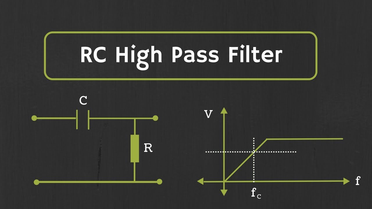
- 📉 Passive filters have limitations such as reduced output signal strength and cut-off frequency dependence on load, which active filters can mitigate.
- 💡 Active filters not only pass certain frequency bands but also provide gain to the input signal, enhancing signal strength.
- 🔌 Op-amps are used in active filters due to their high input impedance and low output impedance, which helps isolate the load from the filter circuitry.
- 🔄 The video demonstrates how to configure an Op-amp as a buffer, acting as a voltage follower with a gain of 1.
- 📌 The gain of an Op-amp in a non-inverting amplifier configuration can be adjusted by varying the feedback resistance and input resistance.
- 📐 The transfer function of an active low pass filter is derived and shown to be Av/√(1+(f/fc)^2), where Av is the voltage gain provided by the Op-amp.
- 🔄 The video explains how to design active filters that can avoid loading effects from both the input and output stages.
- 🎓 An example is provided to calculate the cut-off frequency for an active low pass filter, demonstrating the application of the formula 1/2πRC.
- 🛠️ The video concludes with an exercise for designing a high pass filter with a specified cut-off frequency and gain, encouraging practical application of the concepts discussed.
Q & A
What are the limitations of passive RC low pass and high pass filters?
-The limitations of passive RC filters include the output always being less than the input signal, and the cut-off frequency depending on the load, which can modify the effective resistance and hence the cut-off frequency.
How do active filters overcome the limitations of passive filters?
-Active filters overcome these limitations by using active components like Op-amps and transistors, which provide gain to the input signal and do not have their cut-off frequency affected by the load.
What is the main advantage of using an Op-amp in filter design?
-The main advantage of using an Op-amp is its high input impedance and low output impedance, which allows it to act as a buffer to isolate the load from the filter circuitry.
How is an Op-amp configured as a buffer?
-An Op-amp is configured as a buffer, or a voltage follower, by connecting the input to the non-inverting end and shorting the output to the inverting end, resulting in an output equal to the input with a gain of 1.
What is the formula for the gain of a non-inverting amplifier Op-amp configuration?
-The gain of a non-inverting amplifier Op-amp configuration is given by 1 + (Rf/R1), where Rf is the feedback resistor and R1 is the input resistor.
What is the transfer function of an active low pass filter?
-The transfer function of an active low pass filter is given by Av/√(1+(f/fc)^2), where Av is the voltage gain provided by the Op-amp, which is 1 + Rf/R1.
How is the cut-off frequency of an active low pass filter determined?
-The cut-off frequency (fc) of an active low pass filter is determined by the expression 1/2πRC, where R is the resistor and C is the capacitor in the filter circuit.
What is the difference between an active low pass filter and a passive one in terms of frequency response?
-While both active and passive low pass filters have a cut-off frequency where the output is 0.707 times the maximum value, active filters can also provide gain to the input signal, which passive filters cannot.
How can the effect of loading from the input stage be avoided in an active low pass filter?
-The effect of loading from the input stage can be avoided by connecting the capacitor in the feedback path of the Op-amp, which changes the cut-off frequency to 1/2πRfC, with Rf being the feedback resistor.
What is the transfer function of an active high pass filter?
-The transfer function of an active high pass filter is given by Av * (f/fc)/√(1+(f/fc)^2), where Av is the voltage gain provided by the Op-amp, which is 1 + Rf/R1.
How can higher order active filters be designed?
-Higher order active filters can be designed by cascading first order active filters, which will be discussed in more detail in upcoming videos.
Outlines

Esta sección está disponible solo para usuarios con suscripción. Por favor, mejora tu plan para acceder a esta parte.
Mejorar ahoraMindmap

Esta sección está disponible solo para usuarios con suscripción. Por favor, mejora tu plan para acceder a esta parte.
Mejorar ahoraKeywords

Esta sección está disponible solo para usuarios con suscripción. Por favor, mejora tu plan para acceder a esta parte.
Mejorar ahoraHighlights

Esta sección está disponible solo para usuarios con suscripción. Por favor, mejora tu plan para acceder a esta parte.
Mejorar ahoraTranscripts

Esta sección está disponible solo para usuarios con suscripción. Por favor, mejora tu plan para acceder a esta parte.
Mejorar ahora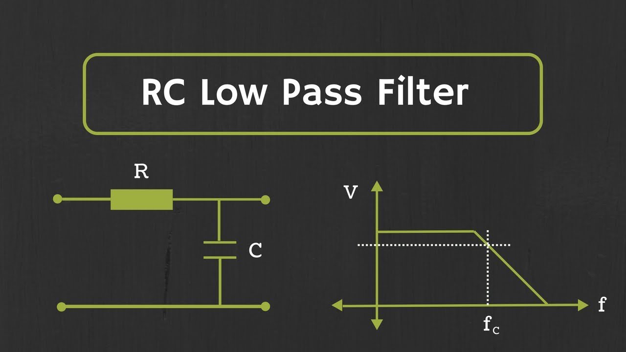


5.0 / 5 (0 votes)
