RC High Pass Filter Explained
Summary
TLDRThis YouTube video from 'All About Electronics' dives into the RC High Pass Filter, explaining how it allows high-frequency signals while attenuating low frequencies. The video covers the frequency response, phase shift, and the derivation of the cut-off frequency equation, fc = 1/2ΟRC. It also guides viewers through designing a high pass filter with a 10 kHz cut-off frequency using a 10-kilo ohm resistor and a 1.5 nF capacitor. The discussion touches on higher-order filters and the importance of buffer isolation to prevent loading effects, with a promise of more on active high pass filters in future videos.
Takeaways
- π‘ The RC High Pass Filter is designed to pass high-frequency signals and attenuate low-frequency signals.
- π At the cutoff frequency, the output of an ideal high pass filter is zero, and it increases as frequency increases, reaching the input value at high frequencies.
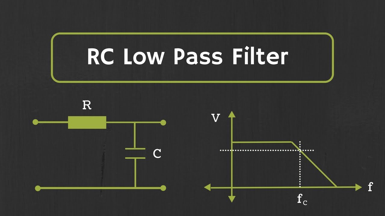
- π§ To create a high pass filter, simply interchange the positions of the resistor and capacitor in a low pass filter circuit.
- βοΈ The voltage divider rule is used to express the output voltage in terms of input voltage, resistance, and capacitive reactance.
- π At very low frequencies, the output voltage is zero due to infinite capacitive reactance, and at very high frequencies, the output equals the input.
- π The frequency response of an actual high pass filter shows a gradual increase from zero at low frequencies to the input value at high frequencies.
- π‘ The cutoff frequency (fc) of a high pass filter is given by the formula fc = 1/(2ΟRC), which is the same as for a low pass filter.
- π The phase of the output signal in a high pass filter changes from leading the input by 90 degrees at zero frequency to being in phase at infinite frequency.
- π οΈ To design a high pass filter with a specific cutoff frequency, choose appropriate R and C values based on the formula fc = 1/(2ΟRC).
- π Higher-order high pass filters can be created by cascading first-order filters, which increases the roll-off rate and reduces output at lower frequencies more sharply.
Q & A
What is the primary function of an RC high pass filter?
-An RC high pass filter primarily passes high-frequency components from the input signal and attenuates or rejects low-frequency components.
How does the frequency response of an ideal high pass filter differ from an actual high pass filter?
-An ideal high pass filter would pass all frequencies above the cutoff frequency and reject all below, while an actual high pass filter has a gradual transition where the output increases from zero at low frequencies to the input value at high frequencies, reaching 0.707 times the input value at the cutoff frequency.
What is the formula for calculating the cutoff frequency of an RC high pass filter?
-The formula for calculating the cutoff frequency (fc) of an RC high pass filter is fc = 1/(2ΟRC), where R is the resistance and C is the capacitance.
How can the position of a resistor and capacitor in a circuit determine whether it's a low pass or high pass filter?
-In a low pass filter, the resistor is in series with the input, and the capacitor is in parallel to the output. In a high pass filter, the positions are interchanged, with the capacitor in series with the input and the resistor to ground.
What is the reactance of a capacitor and how is it calculated?
-The reactance of a capacitor (Xc) is calculated using the formula Xc = 1/(2ΟfC), where f is the frequency and C is the capacitance.
At what frequency does the output of a high pass filter equal the input?
-At very high frequencies, the output of a high pass filter will be approximately equal to the input value.
Why is the phase of the output signal different from the input in a high pass filter?
-The phase of the output signal in a high pass filter is different from the input because the filter not only attenuates low-frequency components but also changes their phase, which can be described by the equation tan^(-1)[ (1/wCR)].
What is the significance of the cutoff frequency in the design of a high pass filter?
-The cutoff frequency is significant in the design of a high pass filter because it determines the point at which the filter starts to pass the signal without significant attenuation, and it is a key parameter in setting the filter's performance characteristics.
How can one design a high pass filter with a specific cutoff frequency?
-To design a high pass filter with a specific cutoff frequency, one needs to select the values of the resistor and capacitor such that the equation 1/(2ΟRC) equals the desired cutoff frequency. Adjustments can be made using a potentiometer for the resistor to fine-tune the cutoff frequency.
What is the roll-off rate of a first-order high pass filter, and how does it compare to higher order filters?
-The roll-off rate of a first-order high pass filter is 20 dB/decade. Higher order filters have a steeper roll-off rate, which means they attenuate frequencies below the cutoff more sharply.
Why might one choose to use a potentiometer instead of a fixed resistor in a high pass filter design?
-Using a potentiometer instead of a fixed resistor allows for the adjustment of the resistance value, which can be used to fine-tune the cutoff frequency of the high pass filter to achieve the exact desired value.
Outlines
π‘ Introduction to RC High Pass Filter
This paragraph introduces the concept of the RC High Pass Filter, which is designed to allow high-frequency signals to pass while attenuating low-frequency signals. The video explains that by simply swapping the positions of a resistor and a capacitor in a circuit, a low pass filter can be converted into a high pass filter. The voltage divider rule is used to derive the output voltage formula, Vout = R*Vin/(R+Xc), where Xc is the reactance of the capacitor. The reactance Xc is given by 1/wc, and the behavior of the filter at extreme frequencies (w=0 and w=β) is discussed. The paragraph concludes with a discussion of the frequency response of both ideal and actual high pass filters, highlighting the cutoff frequency (fc) and the rate of output increase below this frequency.
π Derivation of High Pass Filter Equations
The paragraph delves into the mathematical derivation of the high pass filter's behavior. It starts by restating the voltage divider rule and introduces the concept of reactance Xc. The equation for the cutoff frequency, fc = 1/2ΟRC, is derived by equating the output to be 1/β2 times the input at the cutoff frequency. The discussion then moves to the phase shift introduced by the high pass filter, with the phase equation tan^(-1)[ (1/wCR)] being introduced and derived. The phase behavior at different frequencies (0, wc, and β) is explained, showing how the output signal leads or lags the input signal. The paragraph also includes a practical example of designing a high pass filter with a 10 kHz cutoff frequency, detailing the selection of resistor and capacitor values and the resulting frequency response.
π Designing a High Pass Filter with Variable Cutoff Frequency
This paragraph focuses on the practical application of designing a high pass filter with a variable cutoff frequency. It suggests using a potentiometer instead of a fixed resistor to adjust the cutoff frequency to the desired value. The example given uses a 1.5 nF capacitor and a 20-kilo ohm potentiometer to achieve a cutoff frequency of 10 kHz. The paragraph also touches on the frequency response and output voltage at different frequencies, including at the cutoff frequency and one decade away from it. The discussion concludes with a brief mention of higher order filters and the challenges associated with their design, such as loading effects and the need for isolation between stages, hinting at the use of electrical buffers or active high pass filters for more complex designs.
Mindmap
Keywords
π‘High Pass Filter
π‘Cutoff Frequency
π‘Reactance
π‘Voltage Divider
π‘Decibel
π‘Phase Shift
π‘Transfer Function
π‘Potentiometer
π‘First-Order Filter
π‘Second-Order Filter
π‘Active High Pass Filter
Highlights
Introduction to RC High Pass Filter and its function to pass high-frequency components and attenuate low-frequency components.
Explanation of how to convert a low pass filter into a high pass filter by interchanging the positions of the capacitor and resistor.
Derivation of the voltage divider formula Vout = R*Vin/(R+Xc) to understand the circuit's behavior as a high pass filter.
Discussion of the reactance Xc of the capacitor and its formula Xc = 1/wc.
Analysis of the two extreme cases of reactance at w=0 and w=infinity and their effects on Vout.
Description of the frequency response of an ideal high pass filter and its characteristics.
Comparison between the frequency response of an ideal and an actual high pass filter.
Explanation of the cut-off frequency fc and its equation fc = 1/2ΟRC.
Derivation of the high pass filter equation Vout/Vin = R/(R + Xc) and further simplification to find the cut-off frequency.
Discussion on how the high pass filter changes the phase of the signal and the phase equation tan^(-1)[ (1/wCR)].
Derivation of the phase equation and its implications at different frequencies.
Practical example of designing a high pass filter with a cut-off frequency of 10 kHz.
Explanation of the choice of resistor value to prevent loading the next stage of the circuit.
Calculation of the required capacitor value for the desired cut-off frequency and the selection of a standard value.
Adjustment of the cut-off frequency using a potentiometer for fine-tuning.
Discussion on the frequency response and phase shift at various frequencies for the designed high pass filter.
Introduction to higher order filters and their roll-off characteristics compared to first-order filters.
Explanation of cascading first-order high pass filters to create a second-order high pass filter and its cut-off frequency equation.
Challenges in designing higher order filters and the use of electrical buffers or active high pass filters to overcome them.
Transcripts
Hey friends, welcome to the YouTube channel ALL ABOUT ELECTRONICS.
So, in the last video, we had seen everything about the passive RC low pass filter.
So, in this video, we will learn about the RC High pass filter.
So, as its name suggests, this high pass filter passes the high-frequency components from
the input signal and attenuates or rejects the low-frequency components.
And if we see the frequency response of an ideal high pass filter, it will look like
this.
So, this high pass filter passes all the high-frequency components which are greater than this cutoff
frequency fc.
And it rejects all the frequencies which are less than this cutoff frequency fc.
So, now in the last video, we had seen that by connecting resistor and capacitor in this
fashion, we can design the low pass filter.
So, now just by interchanging the position of this capacitor and resistor, we can convert
this low pass filter into the high pass filter.
So, in this high pass filter, we are applying input signal at this end and we are taking
the output across this resistor.
So, now let's understand how this circuit acts as a high pass filter.
So, just by applying the voltage divider, we can write
Vout as R*Vin/(R+Xc) where Xc is nothing but reactance of this
capacitor.
And we know that this reactance Xc can be given by equation 1/wc.
So, now let's consider two extream cases.
Let's say at w=0, the reactance of this capacitor will be infinity.
and because of that Vout will be equal to zero.
And at w is equal to infinity, the value of this reactance will be zero.
And hence, this Vout will be equal to Vin.
So, as you can see, at low frequency, the output will be approximately equal to zero
and as the frequency increases the output will also increase.
And at high frequencies, the output will be approximately equal to the input value.
So, now earlier we had seen the frequency response of an ideal high pass filter.
But if we see the frequency response of actual high pass filter, it will look like this.
So, at low frequencies, the output will be approximately equal to zero.
And as the frequency increases, the output will also increase.
And at cutoff frequency, the output will be 0.707 or 1/β2 times the input value.
And as we go beyond this cutoff frequency, the output will approximately equal to the
input value.
So, below this cut-off frequency fc, the output will increase at the rate of 20 dB / decade.
So, now this cut-off frequency fc can be given by equation
fc= 1/2ΟRC, which is the same equation that we got for the low pass filter.
So, now let's derive the equation for high pass filter.
So, again we can write this vout as R*Vin/(R+Xc)
Or we can say that, Vout/Vin = R/(R + Xc)
So, now we can write
|Vout/Vin|
= R/β(R^2 + Xc^2) And at the cutoff frequency, the output will
be 1/β2 times the input signal.
So, by putting this value and squaring up at both the sides we can write, 1/2 = R^2/(R^2
+Xc^2) And if we further simplify it then we will
get R^2 = Xc^2 And we know that Xc is nothing but 1/wc
So, we can write this Xc^2 as 1/(w^2*C^2) And if we further simplify it then we will
get w^2 = 1/(R^2*C^2)
And hence, w= 1/RC And if we write this equation in terms of
the frequency, then the cut-off frequency equation will be
1/2ΟRC So, in this way we have derived the expression
for the cut-off frequency of the high pass filter.
So, now this high-pass filter not only attenuates the low-frequency components, but it will
also change their phase.
And the phase of the output signal for the high pass filter can be given by the equation
tan^(-1)[ (1/wCR)].
So, now if you are wondering how we have arrived at this equation, so let's derive this equation.
So, let's once again write Vout as R*Vin/(R+Xc)
Or we can say that Vout/Vin = R/(R+Xc) So, now let's put the value of Xc into this
equation.
So, we will get R/[R+1/(jwC)]
And if we further simplify it then we can write it as
1/[1-j/(wCR)] So, now this Vout/Vin is known as the transfer
function of this high pass filter.
And the phase of this transfer function can be given as
-tan^(-1) [-1/wCR] That is equal to tan^(-1) [1/wCR]
Now, if you see at w=0, 1/wCR will be infinity.
And hence, the value of phase will be 90 degrees.
So, at w=0, the output signal will lead the input by 90 degrees.
So, now at w=wc, this term will be equal to 1, as w will be equal to 1/RC.
And hence the value of phase will be 45 degrees.
And at w is equal to infinity, this 1/wCR will be equal to zero and hence phase will
be equal to 0 degrees.
So, we can say that at w is equal to infinity, the output signal will be in phase with the
input signal.
So, now if you see the phase vs frequency curve, for the high pass filter, it will look
like this.
So, at zero frequency, the phase of the output signal will be 90 degrees.
That means the output signal will leads the input by 90 degrees.
And at the cut-off frequency, if you see, the phase of the output signal will be 45
degrees.
That means the output will lead the input by 45 degrees.
And as we move towards the higher frequencies, the output signal phase will be approximately
equal to input signal phase.
And at infinity, the phase of the output signal will be zero.
So, now as we know about the phase and frequency response of this high pass filter, now let's
take one example based on this high pass filter.
So, now in this example, we have been asked to design the high pass filter which is having
the cut-off frequency of 10 kHz.
So, now we need to select the value of this capacitor and resistor in such a way that
we will get the cut-off frequency of 10 kHz.
So, what we will do, we will arbitrarily choose the value of resistor R as 10-kilo ohm.
And we will decide the value of the capacitor.
So, now you may ask that why I have chosen the value of resistor R as 10-kilo ohm.
The reason is that, if I connect this high pass filter to any other circuit, then the
next stage should not be get loaded by the value of this resistance R.
So, now if I choose the value of resistance R in ohms, then it is quite possible that
my next stage might get loaded.
And if I choose the value of resistance R in Mega ohms, then the value of capacitor
will be very small and it will be so small that the parasitic capacitance will also come
into the picture.
And because of that, the design of this high pass filter will get complicated.
So, the value of R should be in the range of 1- 10-kilo ohms.
So, that is why I have chosen the value of R as 10 kilo-ohms.
Alright, so now the cut-off frequency fc can be given as
1/2ΟRC So, we can say that capacitance C will be
1/2ΟRf And if we put the value of this resistance
and frequency, and if we find the value of capacitance then we will get the value of
C as 1.59 nF
Now, 1.5 nF is the readily available capacitor in the market.
And it is also very nearby to this value of 1.59 nF.
So, we will take the value of capacitance C as 1.5 nF
And earlier we have assumed the value of this resistance R as 10-kilo ohm.
So now, if we put this two values of R and C into this cut-off frequncy equation, then
we will find the cut-off frequency fc as 10.61 kHz.
Which is slightly greater than our required cut-off frequency.
So, now what we can do, we will keep the value of this capacitance C as it is and instead
of this 10-kilo ohm resistance, we will use the 20-kilo ohm POT.
So, just by adjusting this POT, we will get the exact value of 10 kHz.
So, in our design, the value of capacitance should be 1.5 nF and instead of using the
fixed value of the resistor, we will use 20-kilo ohm potentiometer.
And by adjusting the value of this potentiometer, we can get the exact value of this cut-off
frequency of 10 kHz.
So, in this way, we can design the high pass filter of any given cut-off frequency.
So, now if we see the frequency response of this high pass filter, it will look like this.
And our cut-off frequency for this filter is 10 kHz.
So, now let's assume that to this high pass filter we have applied 10 V of a sinusoidal
signal with variable frequency.
So, at very high frequencies, the output will be approximately equal to input.
And at the output, we will get 10 V At the cut-off frequency of 10 kHz, the output
will be 0.707 times the input value.
So, at the output, we will get 7.07 V. And if we go 1 decade away from this 10 kHz
frequency, then let's say at 1 kHz, the output will be 1/10th of this value.
That is 0.707 V.
So, now suppose, in your design if you want that at 1 kHz, your output should be even
much lesser than this 700 mV, then you should go for the higher order filters.
Because for the first order filter if you see, the roll-off is 20 dB/decade.
And as we go for the higher order filters, the roll-off will sharply increase.
And if you see the output at 1 kHz, it will drastically reduce for the higher order filters.
So, just by cascading this first order high pass filters, we can design higher order high
pass filters.
So, let's take the case of second order high pass filter.
So, just by cascading these two high pass filters, we can design the second-order high
pass filter.
And the cut-off frequency of this second order high pass filter can be given by the equation
1/2Οβ(R1C1R2C2) And if R1=R2 and C1=C2, then the cut-off frequency
will be 1/2ΟR1C1
Now, designing this higher order filters is not as simple as it looks like.
Because the next stage might get loaded by the previous stage.
And to eliminate this loading effect, we should isolate two stages.
And we can do so by using the electrical buffer.
Or we can go for the active high pass filter.
And we will learn more about this active high pass filters in the upcoming videos.
So, I hope, in this video, you understood about the passive RC high pass filter.
5.0 / 5 (0 votes)