On load tap changer || Control Circuit Operation || Part -6 || English
Summary
TLDRThis video provides a detailed explanation of the control circuit wiring for an On-Load Tap Changer (OLTC) system. It covers the key components involved, including the OLTC mechanism box, RTCC panel, and DM box, and how they interact to adjust transformer tap positions. The video explains how power flows through the system, the role of contactors, and the operation of the DSS switch to stop the motor once the tap position changes. Viewers will learn both the local and remote control functions and the importance of safety mechanisms in the OLTC operation.
Takeaways
- 😀 The video explains the control circuit wiring for an On-Load Tap Changer (OLTC) in transformers.
- 😀 Power supply starts from the CSS switch and moves to the transformer, powering the RTCC panel and OLTC motor.
- 😀 The RTCC panel has an AC1 contactor that controls the oil tap changer's power supply, with L2 indicating supply off and L1 indicating supply on.
- 😀 The video distinguishes between local and remote operation modes for controlling tap changer settings.
- 😀 In remote mode, raise and lower push buttons on the RTCC panel activate the operation of the motor by energizing the MRCR and MRCL contactors.
- 😀 The DSS switch plays a crucial role in stopping the motor once the desired tap position is reached, with its contacts opening and closing at specific positions.
- 😀 The motor operation involves multiple switches such as RCR and SR, which ensure correct motor movement for raising or lowering tap positions.
- 😀 A plunger mechanism within the DSS switch rotates as the tap position changes, which helps control the motor’s stop function.
- 😀 The video emphasizes the importance of correctly wiring the RTCC panel to the DM box to control motor actions effectively.
- 😀 The next video will focus on the master and follower circuit wiring for the OLTC system, expanding on the concepts introduced in this video.
Q & A
What is the primary purpose of the on-load tap changer (OLTC) in transformers?
-The primary purpose of the on-load tap changer (OLTC) in transformers is to adjust the voltage level of the transformer by changing the tapping positions while the transformer is in operation, without interrupting the power supply.
How does the control circuit wiring for the OLTC work?
-The control circuit wiring for the OLTC involves a series of components, including the RTCC panel, DM box, various contactors, and switches. Power is supplied from the CSS switch to the transformer, and from there, it flows through the RTCC panel and the DM box to control the motor that adjusts the tapping positions.
What role does the AC1 contactor play in the control circuit?
-The AC1 contactor in the RTCC panel is responsible for enabling the power supply to the OLTC. When the CSS3 switch is turned on, the AC1 contactor is energized, closing the contact and allowing the supply to flow to the DM box, indicating that the OLTC supply is on.
What is the function of the DSS switch in the OLTC system?
-The DSS (Dynamic Step Switch) is crucial for stopping the motor once the tapping position has changed. It operates by closing contacts at different stages of the raising or lowering operation and ensures the motor stops once the desired tap position is achieved.
How does the power flow from the RTCC panel to the DM box?
-Once the AC1 contactor in the RTCC panel is energized, power flows from the panel to the DM box. The power supply reaches the motor through various contacts and switches, including the sequence selector switch and the limit switches, which control the direction of the motor.
What is the role of the 'Raise' and 'Lower' push buttons in the RTCC panel?
-The 'Raise' and 'Lower' push buttons in the RTCC panel allow operators to control the adjustment of the tapping position. When the 'Raise' button is pressed, the motor operates to increase the tap position, and similarly, the 'Lower' button adjusts the tap position down.
How is the motor in the DM box energized to change the tapping position?
-The motor in the DM box is energized when the power reaches the MRCR contactor after the 'Raise' or 'Lower' switch is activated, either remotely from the RTCC panel or locally. The energized contactors close, allowing the motor to rotate and change the tap position.
What is the significance of the limit switch (RLS) in the circuit?
-The limit switch (RLS) plays a critical role in controlling the motor's rotation. It ensures that the motor stops once the maximum or minimum tap position has been reached, providing a safety mechanism to prevent over-adjustment.
What happens when the DSS switch contacts close during the raise operation?
-When the DSS switch contacts close during the raise operation, the power flows through the circuit, activating the SR contactor, energizing the motor to move the tapping position. As the operation progresses, additional contacts close to ensure the motor keeps running until the desired position is achieved.
How does the system prevent the motor from continuing once the tap position has been changed?
-Once the desired tap position has been achieved, the DSS switch moves back to its normal position, and the contacts open. This de-energizes the MRCR contactor, opening the contact and stopping the motor from rotating, effectively cutting off power to prevent further movement.
Outlines

Dieser Bereich ist nur für Premium-Benutzer verfügbar. Bitte führen Sie ein Upgrade durch, um auf diesen Abschnitt zuzugreifen.
Upgrade durchführenMindmap

Dieser Bereich ist nur für Premium-Benutzer verfügbar. Bitte führen Sie ein Upgrade durch, um auf diesen Abschnitt zuzugreifen.
Upgrade durchführenKeywords

Dieser Bereich ist nur für Premium-Benutzer verfügbar. Bitte führen Sie ein Upgrade durch, um auf diesen Abschnitt zuzugreifen.
Upgrade durchführenHighlights

Dieser Bereich ist nur für Premium-Benutzer verfügbar. Bitte führen Sie ein Upgrade durch, um auf diesen Abschnitt zuzugreifen.
Upgrade durchführenTranscripts

Dieser Bereich ist nur für Premium-Benutzer verfügbar. Bitte führen Sie ein Upgrade durch, um auf diesen Abschnitt zuzugreifen.
Upgrade durchführenWeitere ähnliche Videos ansehen

Transformer Off Circuit and On Load Tap Changer function, components, installation, operation part1

Simulasi Arduino Menggunakan TinkerCAD - Interface monitoring suhu & Kontrol suhu berbasis LCD I2C

Montagem de QDC com DPS e IDR

vy commodore srs air bag fault

Air Pollution Monitoring System in Tinkercad
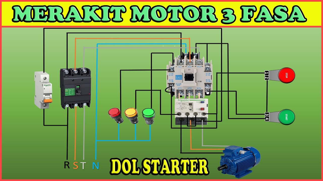
How to assemble a 3-phase motor DOL starter (direct on line) circuit
5.0 / 5 (0 votes)
