Week 10 Q2 Odd 24 25
Summary
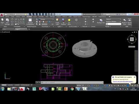
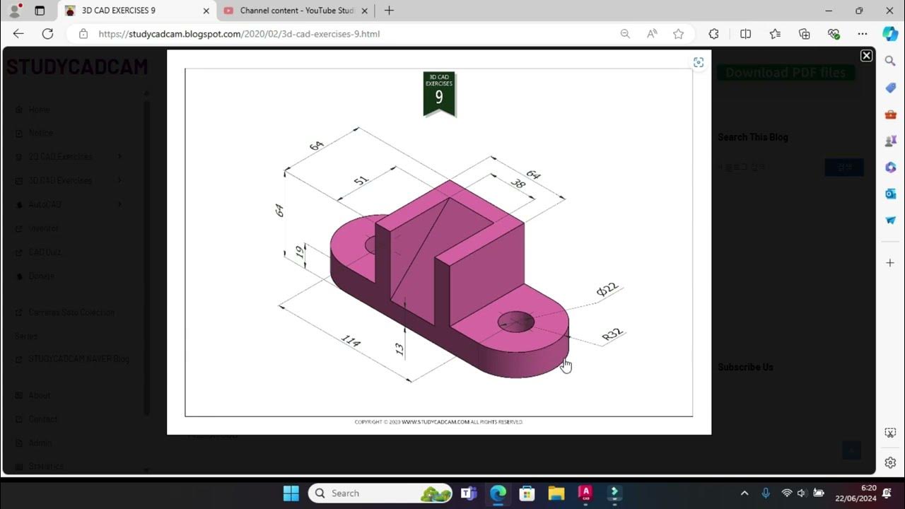
TLDRThis video provides a step-by-step guide for creating a 3D model in AutoCAD using basic geometric shapes. The process begins with drawing a base box and proceeds with the addition of a square box and several cylinders, using the union and subtraction commands to combine and modify the shapes. The user is instructed to adjust the positioning of shapes, move objects, and finalize the design by ensuring all parts are correctly subtracted or united. The result is a precisely constructed 3D model, achieved through detailed manipulation and the use of basic AutoCAD commands.
Takeaways
- 😀 Start by drawing the lower base as a box with length 70, width 70, and height 80.
- 😀 Draw a square box with width 20 and place it above the lower base, with a distance of 40 from the cylinder.
- 😀 Use the 2D wireframe view to draw the initial square box with dimensions of 70 x 20 and height of 40.
- 😀 Switch to front view to draw the cylinder above the box with a diameter of 70 and height of 20.
- 😀 Draw a smaller cylinder (diameter 35, radius 17.5) above the larger cylinder, with a height of 20.
- 😀 Ensure proper placement of the small cylinder by moving it to the center point of the larger cylinder.
- 😀 Use the Union operation to combine the box and cylinder before proceeding with subtraction.
- 😀 Subtract the smaller cylinder from the larger object to complete the hollow section.
- 😀 Draw and subtract a rectangular box from the base with a length of 70, width of 40, and height of 40.
- 😀 Use the Union and Subtract operations to adjust the position and finalize the object shapes.
- 😀 Draw and place a cylinder (radius 20, height 80) in the center of the box to complete the model, then subtract it from the object.
Q & A
What is the first step in the modeling process described in the script?
-The first step is to draw the lower base of the model, starting with a box with a length and width of 70 units, and a height of 80 units.
What tool is used to create the initial box in the design?
-The Box tool is used to create the initial base of the model. The dimensions are specified in the command bar.
How do you create the second part of the model after the base?
-The second part is created by drawing a square box with a width of 20 units and a height of 40 units, followed by a cylinder with a radius of 35 units and a height of 20 units, which is then unified with the box.
How is the cylinder placed relative to the box?
-The cylinder is placed above the box using the front view. The cylinder's radius is set to 35, and its distance from the box is 20 units.
What is the purpose of switching to the 2D wireframe view?
-The 2D wireframe view is used to simplify the visualization and placement of objects like boxes and cylinders. This allows for accurate alignment and positioning in the 3D space.
What is the next step after uniting the box and cylinder?
-After uniting the box and the larger cylinder, a smaller cylinder (with a radius of 17.5) is subtracted from the union to refine the shape.
What is the purpose of the subtraction step in the model?
-The subtraction step removes unnecessary portions from the model, refining the overall shape and ensuring the final object matches the intended design.
How is the second box, used to remove material from the model, positioned?
-The second box is placed in the correct position by first selecting the box tool and setting the length to 70 units, width to 40 units, and height to 40 units. It is then moved into position using the 'Move' command.
What action is performed to finalize the removal of material using the second box?
-Once the second box is in position, it is subtracted from the larger object by selecting the box as the removable object and subtracting it from the main model.
How is the final cylinder integrated into the model?
-The final cylinder, with a radius of 20 units and height of 80 units, is placed at the center of the previously formed box. After proper alignment, it is subtracted from the model to complete the shape.
Outlines

Dieser Bereich ist nur für Premium-Benutzer verfügbar. Bitte führen Sie ein Upgrade durch, um auf diesen Abschnitt zuzugreifen.
Upgrade durchführenMindmap

Dieser Bereich ist nur für Premium-Benutzer verfügbar. Bitte führen Sie ein Upgrade durch, um auf diesen Abschnitt zuzugreifen.
Upgrade durchführenKeywords

Dieser Bereich ist nur für Premium-Benutzer verfügbar. Bitte führen Sie ein Upgrade durch, um auf diesen Abschnitt zuzugreifen.
Upgrade durchführenHighlights

Dieser Bereich ist nur für Premium-Benutzer verfügbar. Bitte führen Sie ein Upgrade durch, um auf diesen Abschnitt zuzugreifen.
Upgrade durchführenTranscripts

Dieser Bereich ist nur für Premium-Benutzer verfügbar. Bitte führen Sie ein Upgrade durch, um auf diesen Abschnitt zuzugreifen.
Upgrade durchführenWeitere ähnliche Videos ansehen

How to draw PVC Valve in AutoCAD 3D. #autocad_hindi_tutorial #autocaddrawing

TUTORiAL MEMBUAT PiSTON, BELAJAR BERSAMA - AUTOCAD 2017

Autocad 2dimensional to 3dimensional beginner # 42 mechanical engineering

autocad tutorials for beginners

TUTORIAL AUTODESK INVENTOR UNTUK PEMULA PART 1

Tutorial Autocad 3D II Studycadcam Exercise 9
5.0 / 5 (0 votes)
