TUTORIAL AUTODESK INVENTOR UNTUK PEMULA PART 1
Summary
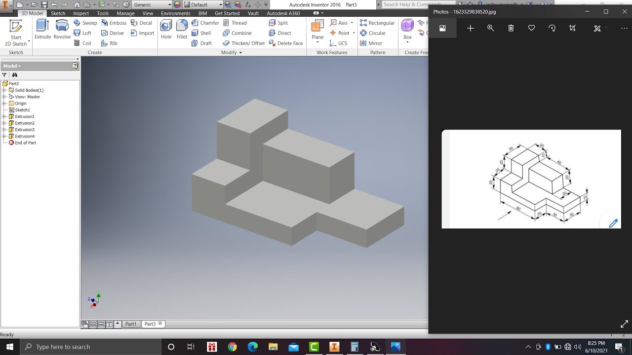
TLDRThis tutorial walks users through creating a simple 3D model using Autodesk Inventor 2017. The instructor demonstrates how to work with isometric drawings and various dimensions, starting with a basic rectangle sketch and adding specific measurements. The guide covers techniques like using the isometric view, creating half-circles, and adding intricate details, such as thickness adjustments and direction settings. It provides step-by-step instructions on rotating the model and finalizing the design. The video encourages viewers to practice these skills, like making cuts and adjustments, to improve their 3D modeling proficiency.
Takeaways
- 😀 The tutorial aims to create a simple 3D model using Autodesk Inventor 2017.
- 🔧 The model is built using student-friendly methods and an isometric drawing for guidance.
- 📏 The process begins by creating a rectangular sketch with dimensions of 96mm x 1064mm.
- 🛠️ Various tools such as the rectangle and line tools are used to construct the model's framework.
- 📐 The tutorial emphasizes setting correct dimensions for precise modeling (e.g., 6mm thickness, 216mm extension).
- 🖼️ Switching to isometric view helps visualize the model from different perspectives.
- 📝 Multiple dimensions and shapes, including half circles and rectangles, are employed to refine the model's geometry.
- 🔄 Users are guided on how to rotate and navigate the model in a 360-degree view.
- ✂️ The tutorial demonstrates creating a cutout section for further refinement of the 3D model.
- 📤 Finally, the model is exported, and the process is wrapped up with a reminder to share, like, and comment on the video.
Q & A
What software is being used in the tutorial?
-The tutorial uses Autodesk Inventor 2017 to create a 3D model.
What kind of model is the user creating in the tutorial?
-The user is creating a simple 3D model using an isometric drawing.
What is the initial step in the modeling process?
-The first step is to create a sketch, starting with a rectangle at the origin point.
How are the dimensions for the rectangle set?
-The rectangle is set to 96 millimeters for one dimension and 1064 millimeters for the vertical dimension.
What feature is used after sketching the rectangle?
-The user applies an extrusion feature to create a 3D body, extending the model by 216 millimeters.
How does the tutorial instruct the user to view the model?
-The tutorial advises switching to isometric view to better visualize the 3D model.
What is the next feature added after the base extrusion?
-The tutorial adds a second sketch and extrudes it to create a plate with a 6-millimeter thickness.
How are the corners of the new sketch created?
-Corners are defined using a two-point rectangle tool, ensuring alignment with the existing geometry.
What is the role of the half-circle feature in the model?
-A half-circle is added to create rounded edges or a cutout in the model.
How can the model be rotated for better inspection?
-The model can be rotated 360 degrees by using the mouse wheel for better viewing angles.
Outlines

This section is available to paid users only. Please upgrade to access this part.
Upgrade NowMindmap

This section is available to paid users only. Please upgrade to access this part.
Upgrade NowKeywords

This section is available to paid users only. Please upgrade to access this part.
Upgrade NowHighlights

This section is available to paid users only. Please upgrade to access this part.
Upgrade NowTranscripts

This section is available to paid users only. Please upgrade to access this part.
Upgrade NowBrowse More Related Video
Learn autodesk inventor 3dimensional # 13 mechanical engineering
PEN in | Autodesk Inventor CAD
Tutorial Drawing #1 Mengubah Ukuran Kertas dan Garis Tepi Di Autodesk Inventor Indonesia

Membuat Augmented Reality dengan Unity 3D

Computer Mouse Surface Modelling in Creo 3.0 | Creo Beginner Tutorial 2021

Create Emotion Recognition Mobile App || MIT App Inventor || Personal Image Classifier Extension[AI]
5.0 / 5 (0 votes)