Hexagonal nut
Summary
TLDRThis video tutorial guides viewers on how to draw a hexagonal nut of size M30, covering the front, top, and side views. The tutorial emphasizes precise measurements, such as a 30-degree angle and threading circles with specific radii. Key details like chamfering, radius markings, and the correct use of line weights (dark and medium dark) are explained for clarity. The video also includes step-by-step instructions for drawing the nut's features, ensuring that viewers can accurately visualize and create a technical drawing of the hexagonal nut.
Takeaways
- 😀 Start by drawing a hexagon for the top view of the hexagonal nut, with a side length of 24 units (half of 48, calculated from 1.5 times the diameter plus 3).
- 😀 Use a 30° angle with the vertical to determine the sides of the hexagon in the top view.
- 😀 The distance between the flats of the hexagon is 1.5D + 3 (48 units for an M30 nut).
- 😀 After obtaining the hexagon, project lines to create the front view of the nut.
- 😀 The height of the nut in the front view is equal to the diameter (D=30), but it can range from 0.7D to D.
- 😀 Use 60° angles with the horizontal lines for accurate projections in the front view.
- 😀 For chamfering, draw circles in the top view and extend lines to create a 30° angle at the edges.
- 😀 The outer circle for threading should be 3/4 of the diameter (36 units), while the inner circle is dark and represents 0.8D (24 units).
- 😀 The front view should also show threading, and the inner circle for threading should be emphasized with a dark line.
- 😀 In the side view, use a 45° angle to extend and draw two rectangles, ensuring the threading is visible with dotted lines.
- 😀 Always make sure to properly darken the bottom line of the side view and the threading to complete the technical drawing of the nut.
Q & A
What is the first step in drawing a hexagonal nut according to the script?
-The first step is to draw the top view of the hexagonal nut, starting by drawing a hexagon. The size 'd' is given as 30, and a measurement of 1.5d plus 3 is used for the distance between flats.
What measurement is used for the hexagon in the top view?
-The measurement used for the hexagon in the top view is 48, calculated as 1.5d plus 3, where 'd' is 30.
How is the side of the hexagon determined in the drawing?
-The side of the hexagon is determined by drawing two lines at a 30-degree angle with the vertical, which will intersect to form the sides of the hexagon.
What is the height 'd' in the front view of the hexagonal nut?
-The height 'd' in the front view is 30, and it can vary between 0.7d and d, but for this drawing, the height is taken as d.
Why is a chamfer drawn in the front view, and how is it created?
-A chamfer is drawn at a 30-degree angle in the front view to represent the beveled edges of the nut. To create the chamfer, a circle is drawn in the top view, and the 30-degree line is extended to intersect at the correct point.
What is the purpose of drawing a circle in the top view when creating the chamfer?
-The circle in the top view is used to define the radius for the chamfer. This helps in drawing the correct angle and ensuring that the chamfer meets at the proper intersection with the nut's edges.
What is the significance of the 60-degree angle used in the front view?
-The 60-degree angle is used to draw the radii at the edges of the nut in the front view. It ensures that the curves are properly aligned with the shape of the nut.
How should the threading be represented in the drawing?
-The threading is represented by two circles: one with a radius of 15 for the outer circle (drawn 3/4 dark) and another with a radius of 12 for the inner circle (drawn fully dark).
What differentiates the dark and medium dark circles in the drawing of the hexagonal nut?
-In the hexagonal nut drawing, the outer circle is drawn medium dark (3/4 dark), while the inner circle is fully dark to distinguish between the outer and inner parts of the nut.
How is the side view of the hexagonal nut drawn?
-In the side view, a 45-degree angle is used to extend two rectangles. The threading is then represented with dotted lines, and a curve is drawn at a distance of 'd' from the center to complete the side view.
Outlines

هذا القسم متوفر فقط للمشتركين. يرجى الترقية للوصول إلى هذه الميزة.
قم بالترقية الآنMindmap

هذا القسم متوفر فقط للمشتركين. يرجى الترقية للوصول إلى هذه الميزة.
قم بالترقية الآنKeywords

هذا القسم متوفر فقط للمشتركين. يرجى الترقية للوصول إلى هذه الميزة.
قم بالترقية الآنHighlights

هذا القسم متوفر فقط للمشتركين. يرجى الترقية للوصول إلى هذه الميزة.
قم بالترقية الآنTranscripts

هذا القسم متوفر فقط للمشتركين. يرجى الترقية للوصول إلى هذه الميزة.
قم بالترقية الآنتصفح المزيد من مقاطع الفيديو ذات الصلة

How to construct a metric bolt and nut from just the M value
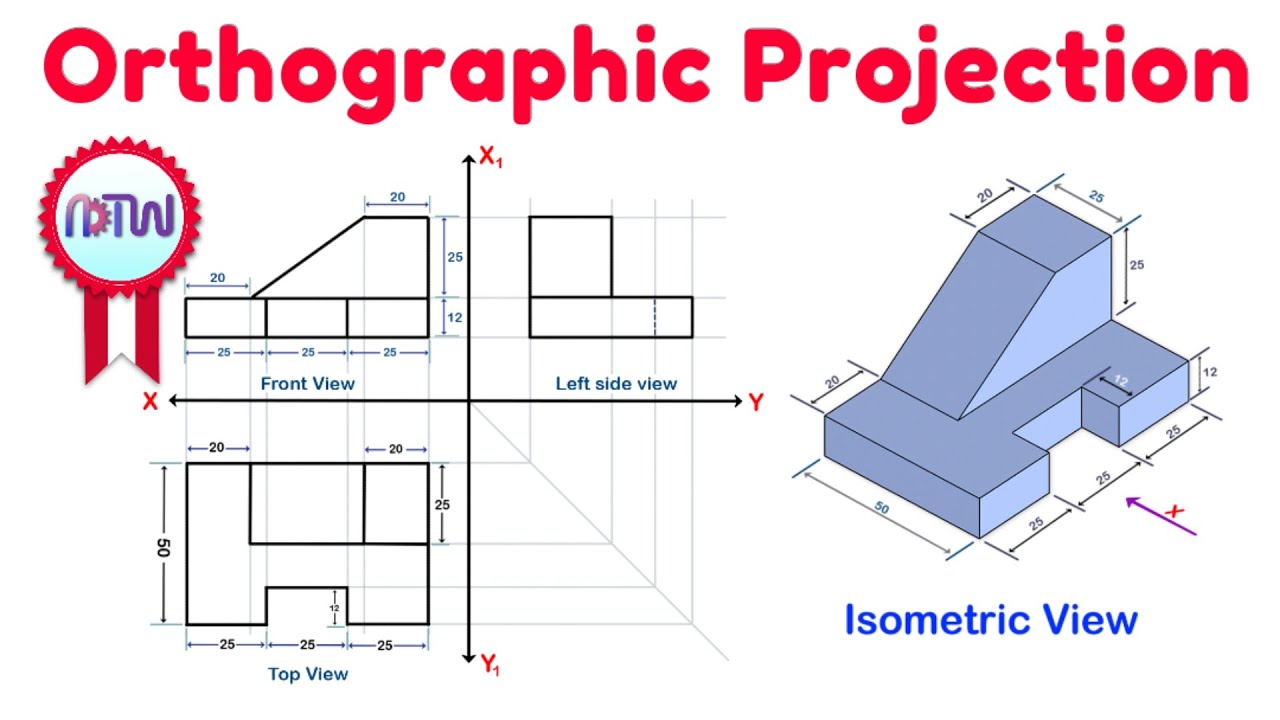
Orthographic Projection from isometric view in Engineering drawing
Orthographic Projection Explained

Isometric View | How to Construct an Isometric View of an Object
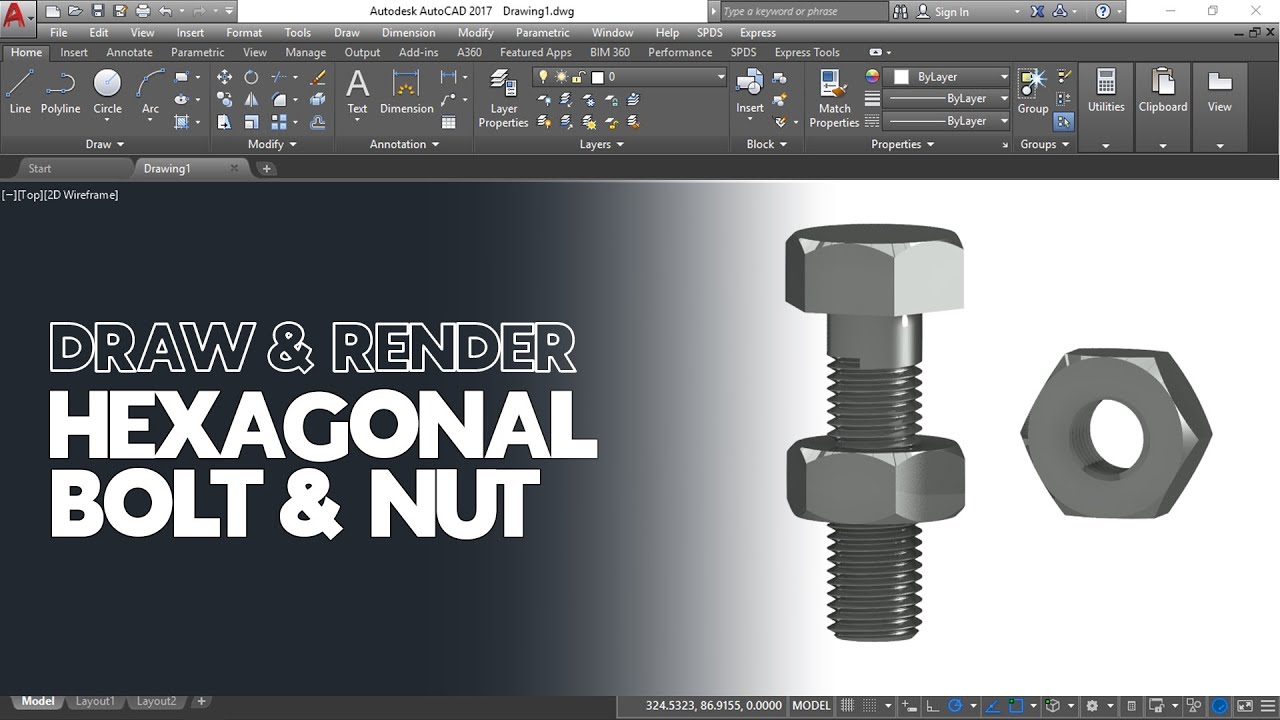
Cara Gambar dan Render Hexagonal Mur dan Baut di AutoCAD

ORTHOGRAPHIC DRAWING EXAMPLE
5.0 / 5 (0 votes)
