Isometric View | How to Construct an Isometric View of an Object
Summary
TLDRIn this tutorial, viewers learn how to construct an isometric view from orthographic projections. The video demonstrates the step-by-step process, starting with creating the isometric axes using a protractor and ruler. It explains how to draw the front and top views, emphasizing key points such as the proper planes for these views. The tutorial details how to draw the object’s features, like slots and base thickness, and finishes with an isometric view. Viewers will understand the essential techniques to represent a 3D object accurately using isometric projection.
Takeaways
- 😀 Create isometric axes by drawing a horizontal line, marking a center point, and using a protractor to set 30-degree and 90-degree angles.
- 😀 The X-axis is defined by the line at 30 degrees, the Y-axis by the 90-degree line, and the Z-axis by the remaining line.
- 😀 The front view should be drawn in the XY or YZ plane, but never in the XC plane.
- 😀 The top view of the object is always drawn in the XZ plane, following the first angle method.
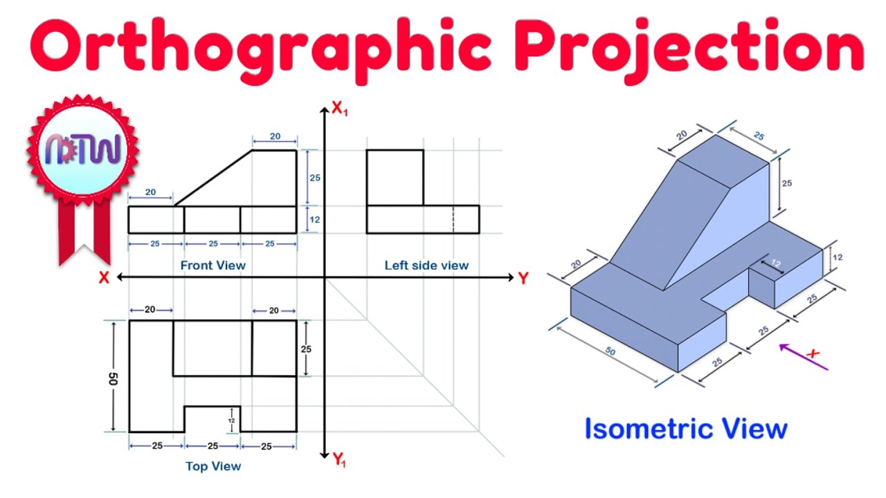
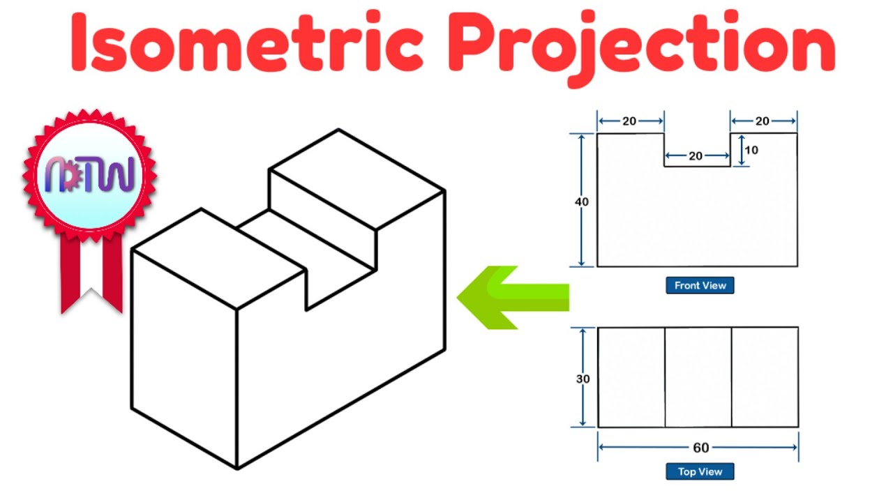
- 😀 The front view (top figure) and top view (bottom figure) are used to construct the isometric view.
- 😀 Draw the top view by outlining the object’s dimensions (75mm length and 50mm width) on the XZ plane.
- 😀 Mark the position of features like slots, ensuring they are 25mm from the edge, and draw them accurately on the top view.
- 😀 The base thickness (12mm) should be added to the top view outline to complete the base for the isometric view.
- 😀 Non-visible lines should be removed to simplify and clarify the drawing, making the final view easier to interpret.
- 😀 The top portion of the object is a 25mm wide rectangle placed 20mm from the base, with a height of 25mm from the base.
- 😀 Use a drafter to mark and extend the features of the object accurately, ensuring the final isometric view matches the orthographic projections.
Q & A
What is the first step in constructing an isometric view from orthographic projections?
-The first step is to create the isometric axis by drawing a horizontal line, marking a center point, and then using a protractor to mark 30-degree angles on both sides of the center point, along with a 90-degree mark.
How do you identify the X, Y, and Z axes in the isometric view?
-The line passing through the 30-degree mark will be the X-axis, the line passing through the 90-degree mark will be the Y-axis, and the remaining line will be the Z-axis.
Why is the front view drawn in the XY or YZ plane, but not in the XC plane?
-The front view is drawn in the XY or YZ planes because these are the planes that provide the necessary perspective for visualizing the object in an isometric view. The XC plane is not suitable for this purpose.
Where should the top view of an object always be drawn in an isometric projection?
-The top view of an object should always be drawn in the XZ plane in an isometric projection.
What dimensions are required to draw the outline of the top view of the object?
-To draw the outline of the top view, you need to know the total length and width of the object. For example, a length of 75 mm and width of 50 mm would result in a rectangle of these dimensions.
How do you construct the slot on the top view of the object?
-To construct the slot, locate its position by measuring from the edge (e.g., 25 mm), then draw parallel lines perpendicular to the edge of the outline. The slot dimensions are also crucial, such as 25 mm in length and 12 mm in width.
How is the thickness of the base represented in the isometric view?
-The thickness of the base is represented by extending each edge of the outline vertically by the thickness amount (e.g., 12 mm). This creates a more defined outline for the base in the isometric view.
What should be done to make the isometric drawing clearer and easier to understand?
-Non-visible lines should be removed from the drawing to make it cleaner and easier to understand.
How do you construct the top portion of the object from the top view?
-To construct the top portion, mark the distance from the base (e.g., 20 mm) and draw a rectangle parallel to the Z-axis and the X-axis with the required dimensions (e.g., 25 mm in width and 20 mm from the base).
What should be done if the top portion of the object is inclined?
-If the top portion is inclined, draw the appropriate angled lines based on the inclination, as indicated by the front view.
Outlines

This section is available to paid users only. Please upgrade to access this part.
Upgrade NowMindmap

This section is available to paid users only. Please upgrade to access this part.
Upgrade NowKeywords

This section is available to paid users only. Please upgrade to access this part.
Upgrade NowHighlights

This section is available to paid users only. Please upgrade to access this part.
Upgrade NowTranscripts

This section is available to paid users only. Please upgrade to access this part.
Upgrade NowBrowse More Related Video
Orthographic Projection from isometric view in Engineering drawing
Isometric Projection in Engineering Drawing | isometric projection 3D from orthographic view

Exercise 1.1 Orthographic Drawing

Sectional Drawing/Engineering Drawing N3/Part 1️⃣

ORTHOGRAPHIC DRAWING EXAMPLE
Orthographic Projection Explained
5.0 / 5 (0 votes)