How to construct a metric bolt and nut from just the M value
Summary
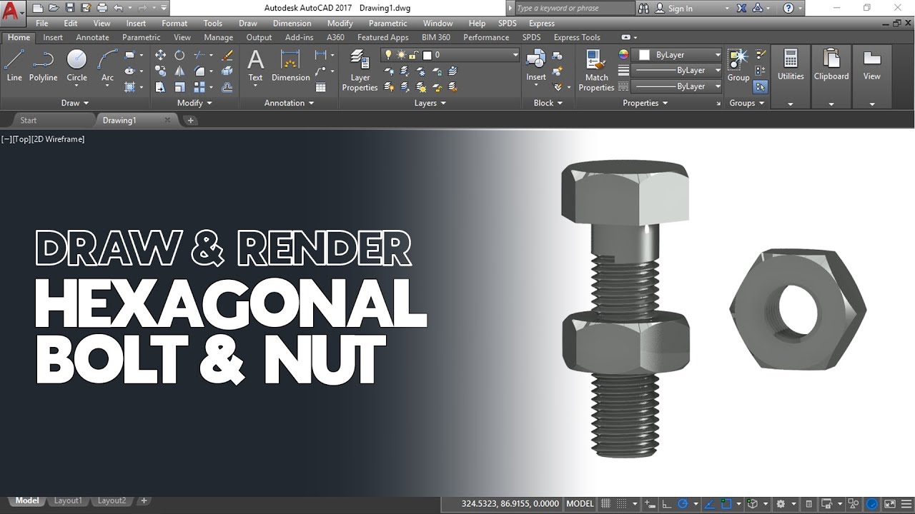
TLDRThis video tutorial walks through the detailed process of drawing a standard hexagonal bolt and its corresponding nut using the metric system. Starting with the M16 bolt, the guide explains how to calculate the hexagon's flat edges, draw the bolt's top and front views, and construct the thread using specific formulas. The video emphasizes key measurements like the diameter of the shaft (M value) and provides step-by-step instructions for drawing the rounded top, shaft, and threaded sections. By the end, viewers will have a complete understanding of how to represent bolts and nuts accurately in technical drawings.
Takeaways
- 😀 The hexagonal bolt consists of a head, shaft, and thread. The head is hexagonal, and the thread holds the bolt and nut together.
- 😀 The M value of a bolt refers to its diameter. For example, an M16 bolt has a 16mm diameter shaft.
- 😀 To find the distance between two flat edges of a hexagon on a bolt, multiply the M value by 1.5. For an M16 bolt, this gives a distance of 24mm.
- 😀 Use a compass set to half of the 'across the flats' distance (12mm for M16) to draw a circle, which helps construct the hexagonal shape of the bolt.
- 😀 A 60-degree set square is used to construct the hexagon by drawing tangents from the circle's edge to form the six sides.
- 😀 The top view of the bolt features three faces of the hexagonal head, and the head's ends are slightly angled down.
- 😀 To draw the front view of the bolt, project the corners of the hexagon down and use a calculated height for the bolt head (M value * 0.7).
- 😀 The top of the bolt head has rounded corners, and small arcs are drawn using a compass to match the correct shape of these curves.
- 😀 The shaft's diameter is the same as the M value, and it's drawn with its lines parallel and 16mm wide for an M16 bolt.
- 😀 Threading on the bolt is indicated by standard thread lines. The length of the thread is based on the specific question, and it's calculated using the M value multiplied by 0.1 to define the distance from the edges to the thread lines.
Q & A
What is the first step in drawing a bolt according to the script?
-The first step is to determine the top view of the bolt, which involves calculating the distance between the two flat edges of the hexagon by multiplying the M value of the bolt by 1.5.
What does the M value of a bolt represent?
-The M value of a bolt represents the diameter of the shaft of the bolt in millimeters.
How do you calculate the distance across the flats of a hexagonal bolt head?
-The distance across the flats is calculated by multiplying the M value of the bolt by 1.5. For an M16 bolt, this would be 16 × 1.5, resulting in 24 millimeters.
What is the purpose of using a 60-degree set square in the drawing process?
-The 60-degree set square is used to construct the hexagon around the circle in the top view of the bolt, ensuring the sides of the hexagon touch the edge of the circle at 60-degree angles.
How is the height of the bolt head determined?
-The height of the bolt head is calculated by multiplying the M value by 0.7. For an M16 bolt, this would be 16 × 0.7, resulting in 11.2 millimeters, rounded to 11 millimeters.
Why is the top of the bolt head rounded in the drawing?
-The top of the bolt head is rounded to accurately represent the rounded edges of the actual bolt head, which is a characteristic feature of standard bolts.
How do you draw the small arcs at the top of the bolt head?
-To draw the small arcs, you use a compass to create arcs from the points where construction lines meet, ensuring the arcs touch the top line of the bolt head.
What is the function of the 30-degree lines in the drawing process?
-The 30-degree lines are used to show the edge of the top of the bolt and help complete the top view by connecting the arcs formed at the top of the bolt head.
What is the significance of the thread in the bolt design?
-The thread allows the bolt to screw into a nut or another threaded component, ensuring the bolt holds together the parts it is meant to secure.
How do you indicate the thread in the drawing?
-The thread is indicated by drawing two small construction lines 1.5 millimeters from each side of the shaft, and a 45-degree angle at the end of the bolt to represent the tapering of the thread.
Outlines

This section is available to paid users only. Please upgrade to access this part.
Upgrade NowMindmap

This section is available to paid users only. Please upgrade to access this part.
Upgrade NowKeywords

This section is available to paid users only. Please upgrade to access this part.
Upgrade NowHighlights

This section is available to paid users only. Please upgrade to access this part.
Upgrade NowTranscripts

This section is available to paid users only. Please upgrade to access this part.
Upgrade NowBrowse More Related Video


5.0 / 5 (0 votes)