Cara membuat LOGO dan Tulisan pada software Mastercam 2017 - Logo Barcelona
Summary
TLDRThis video tutorial provides a detailed guide on creating logos and text in Mastercam for CNC machining. It covers the process of importing a PNG or JPG image, converting it into vectors, and scaling it to fit the workpiece. The video walks through setting up the workpiece, creating tool paths for contouring and pocketing, and adjusting parameters for optimal results. Finally, it demonstrates how to simulate the machining process and make necessary adjustments to ensure accurate cuts, leading to the successful creation of a CNC-machined logo.
Takeaways
- 😀 Import your image file (PNG or JPG) into Mastercam using the 'R to Vector' option.
- 😀 Adjust the resolution of the image to 100 dpi for better accuracy when converting to vector.
- 😀 Use the 'Arc' option for curves and 'Spine' for more complex shapes in Mastercam.
- 😀 Scale the imported image by using the 'Transform' tool, making sure the final size fits your workpiece (e.g., 100x100 mm).
- 😀 Create a rectangular box to help with scaling the image to the desired size on the workpiece.
- 😀 Extrude the workpiece, set the material thickness (e.g., 10 mm), and adjust the Z-axis position accordingly.
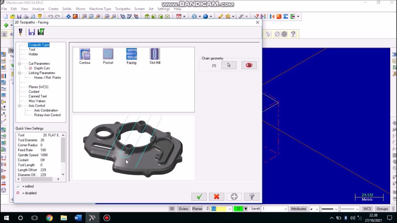
- 😀 Use the 'Contour' toolpath to program the outer perimeter of the logo, choosing the correct tool size (e.g., 6 mm diameter).
- 😀 Modify tool parameters such as feed rate, RPM, and depth of cut to suit the job for clean cutting.
- 😀 For inner designs, use the 'Pocket' operation to clear material and create details, adjusting depth and toolpath parameters.
- 😀 Simulate the toolpaths in Mastercam to verify the program and make adjustments if needed before actual machining.
- 😀 Ensure to adjust the lead-in/lead-out settings in the tool parameters to avoid unexpected results during simulation.
Q & A
What is the first step in creating a logo using Mastercam as shown in the tutorial?
-The first step is importing the PNG or JPG image into Mastercam using the 'R to Vector' function, which converts the image into a vector format for further manipulation.
How do you adjust the resolution of the imported image?
-You can adjust the resolution of the imported image by selecting the appropriate DPI (dots per inch). In this case, a resolution of 100 DPI is chosen for clarity and precision.
What is the purpose of scaling the image in the tutorial?
-The image is scaled to fit the desired workpiece size, such as a 100x100 mm area. Scaling ensures that the logo is appropriately sized to match the machining environment.
Why is the 'Arc' option preferred over 'Spine' for the vectoring process?
-The 'Arc' option is preferred because it offers better accuracy for curved lines, which are commonly found in logos and text designs. This choice ensures smoother curves.
What role does the 'Move' function serve in this tutorial?
-The 'Move' function is used to reposition the logo and adjust its placement within the workpiece area. This allows for accurate alignment before machining.
How does the user ensure the workpiece is the correct size for the logo?
-The user adjusts the size of the logo using scaling and verifies it by comparing it against a 100x100 mm rectangle, ensuring that the image fits well within the workpiece dimensions.
What is the importance of adjusting the Z-height of the workpiece in this process?
-Adjusting the Z-height allows for proper clearance when machining. The user raises and lowers the Z-height to ensure the logo is positioned correctly relative to the material block.
What is the significance of the extruding step in creating the 3D model?
-Extruding the material block creates the three-dimensional shape of the logo. This is crucial for defining the depth and structure of the logo as it will be machined.
Why does the tutorial suggest using the 'Pocket' operation for the logo?
-The 'Pocket' operation is used because it allows for precise cutting of the logo's inner details, which is especially important for logos with intricate shapes and designs.
What adjustments are made to the tool parameters for engraving the logo?
-The tool parameters, such as the diameter and cutting depth, are adjusted to suit the logo's design. A tool diameter of 6 mm is chosen, with a cutting depth that ensures proper engraving without overcutting.
How does the user simulate the machining process in Mastercam?
-The user simulates the machining process by running a simulation to visualize how the tool will interact with the material. This step helps identify any potential issues, such as incorrect tool paths or depth settings.
Outlines

هذا القسم متوفر فقط للمشتركين. يرجى الترقية للوصول إلى هذه الميزة.
قم بالترقية الآنMindmap

هذا القسم متوفر فقط للمشتركين. يرجى الترقية للوصول إلى هذه الميزة.
قم بالترقية الآنKeywords

هذا القسم متوفر فقط للمشتركين. يرجى الترقية للوصول إلى هذه الميزة.
قم بالترقية الآنHighlights

هذا القسم متوفر فقط للمشتركين. يرجى الترقية للوصول إلى هذه الميزة.
قم بالترقية الآنTranscripts

هذا القسم متوفر فقط للمشتركين. يرجى الترقية للوصول إلى هذه الميزة.
قم بالترقية الآنتصفح المزيد من مقاطع الفيديو ذات الصلة
5.0 / 5 (0 votes)


