RC Low Pass Filter Explained

ALL ABOUT ELECTRONICS
20 Aug 201715:18

Summary

TLDRThis video from the 'All About Electronics' YouTube channel delves into the fundamentals of passive electronics filters, specifically focusing on low-pass filters. It explains the concept of filters that allow low-frequency signals while attenuating higher ones. The script covers the types of filters, including low-pass, high-pass, band-pass, and band-reject, and emphasizes the distinction between active and passive filters. It then provides an in-depth look at the first-order RC low-pass filter, detailing its design, frequency response, and phase shift characteristics. The video also illustrates how to calculate the -3dB frequency and output voltage for a given input signal, offering practical insights into filter design and its applications.

Takeaways

  • 🔧 Passive electronic filters are circuits that pass certain frequency components while rejecting or attenuating others.
  • ⚙️ Filters are classified into four types: Low Pass Filter, High Pass Filter, Band-Pass Filter, and Band-Reject Filter.
  • 📉 A Low Pass Filter passes signals from 0 Hz up to a cutoff frequency and attenuates higher frequencies.
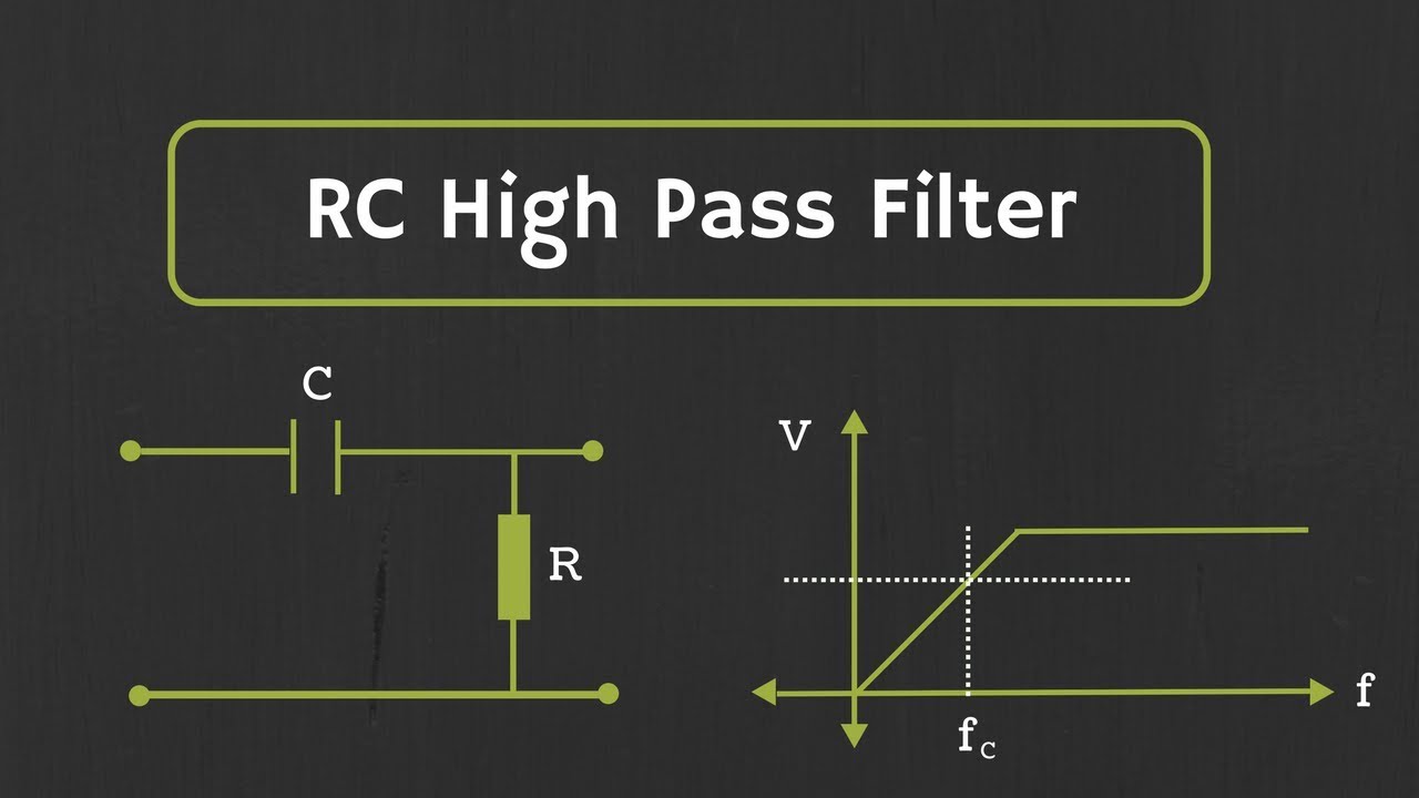
  • 📈 A High Pass Filter allows signals above a cutoff frequency to pass, while attenuating lower frequencies.
  • 🔊 A Band-Pass Filter passes frequencies within a specific range and rejects those outside of it.
  • 🔇 A Band-Reject Filter does the opposite, rejecting frequencies within a specific range and passing others.
  • 📏 The cutoff frequency for a first-order RC low pass filter is determined by the formula 1/(2πRC).
  • 🔬 Active filters use active components like Op-Amps and transistors, providing gain, whereas passive filters use resistors, capacitors, and inductors, and output less than the input.
  • 📉 The output of a low-pass filter decreases as frequency increases, with the output at the cutoff frequency being 0.707 times the input.
  • 🎚️ Higher-order filters provide sharper roll-off, with attenuation increasing by 20 dB/decade for each order.

Q & A

  • What is an electronic filter and what does it do?

    -An electronic filter is a circuit that allows certain frequency components to pass through while rejecting or attenuating all other frequency components. It processes the input signal by filtering out unwanted frequencies.

  • How many types of filters are mentioned in the script, and what are they?

    -Four types of filters are mentioned: Low Pass Filter, High Pass Filter, Band Pass Filter, and Band Reject Filter. Each type is designed to pass or reject specific frequency bands.

  • What is the primary difference between an active filter and a passive filter?

    -Active filters are designed using components like Op-Amp and transistors, which can provide gain to the input signal. Passive filters, on the other hand, are designed using components like resistors, capacitors, and inductors, and the output is always less than the input.

  • What is the formula for calculating the cut-off frequency of a first-order low-pass filter?

    -The cut-off frequency (fc) of a first-order low-pass filter is given by the formula fc = 1/(2πRC), where R is the resistance and C is the capacitance in the filter circuit.

  • What is the significance of the -3dB frequency in the context of filters?

    -The -3dB frequency, also known as the cut-off frequency, is the frequency at which the output is 0.707 times the input, indicating a 3dB reduction in amplitude. It is a key parameter in determining the filter's performance.

  • How does the phase of the output signal change as the input frequency increases in a low-pass filter?

    -In a low-pass filter, as the input frequency increases, the phase of the output signal lags behind the input signal. At the cut-off frequency, the phase lag is -45 degrees, and it approaches -90 degrees at very high frequencies.

  • What is the output voltage of a 10 V, 2 kHz sinusoidal input signal applied to the given low-pass filter in the script?

    -The output voltage for a 10 V, 2 kHz sinusoidal input signal applied to the given low-pass filter is 6.22 V, as calculated using the formula for output voltage in the script.

  • How does the attenuation rate change with the order of the filter?

    -The attenuation rate increases with the order of the filter. For an nth order filter, the roll-off rate is -20*n dB/decade, meaning higher order filters provide a sharper roll-off and greater attenuation at higher frequencies.

  • What is the purpose of cascading first-order low-pass filters to create a higher order filter?

    -Cascading first-order low-pass filters increases the overall order of the filter, which results in a sharper roll-off and greater attenuation at higher frequencies, thus improving the filter's performance.

  • Why is it important to consider loading effects when designing higher order filters by cascading first-order filters?

    -Loading effects occur when the input impedance of the second stage affects the output impedance of the first stage, potentially degrading the filter performance. To minimize this, the value of R2 should be at least 10 times R1, or active filters can be used to provide buffering between stages.

Outlines

00:00

🔌 Introduction to Passive Electronics Filters

This paragraph introduces the concept of electronic filters, which are circuits designed to allow certain frequency components to pass while attenuating others. It explains that filters can be categorized into four types based on the frequency band they allow: Low Pass, High Pass, Band Pass, and Band Reject filters. The focus then shifts to the Low Pass Filter, which passes low-frequency signals up to a cut-off frequency and rejects higher frequencies. The paragraph also distinguishes between active and passive filters, with active filters providing gain to the input signal and passive filters having an output that is always less than the input. The RC low pass filter is highlighted as the main subject for the video, explaining its design and function.

05:04

📡 Understanding the RC Low Pass Filter's Operation and Characteristics

This paragraph delves into the workings of the first-order RC low-pass filter, describing its circuitry and how it acts to pass low-frequency signals while attenuating higher frequencies. The output voltage formula is provided, showing the relationship between the input voltage, the reactance of the capacitor, and the resistor. The behavior of the filter at different frequency ranges is explained, including how the output voltage decreases as frequency increases, approaching zero at very high frequencies. The paragraph also discusses the frequency response of the ideal low-pass filter and the actual response, introducing the concept of the cut-off frequency (-3dB frequency) and how it is derived from the filter's components.

10:11

📚 Example Calculation and Higher-Order Filter Considerations

The final paragraph presents an example calculation to determine the -3dB frequency for a given low-pass filter and to find the output voltage for a specific input signal. It provides the formula for the cut-off frequency and demonstrates its application using given values of resistance and capacitance. The example includes calculating the reactance at a specific frequency and using it to find the output voltage for a 10V, 2 kHz sinusoidal input signal. The paragraph concludes with a discussion on the benefits of higher-order filters for achieving a sharper roll-off and the considerations involved in designing them, such as minimizing loading effects and the use of active filters as buffers.

Mindmap

Keywords

💡Passive Electronics Filters

Passive electronics filters are circuits that allow certain frequency components to pass through while attenuating or rejecting others. They are a fundamental concept in the video, which focuses on the types and characteristics of these filters. In the script, the concept is introduced as the basis for classifying filters into four types, including low pass, high pass, band pass, and band reject filters.

💡Low Pass Filter

A low pass filter is a type of passive electronics filter that allows low-frequency signals to pass through while attenuating higher frequencies. It is central to the video's theme, as the script discusses its characteristics, such as passing signals from 0 Hz up to a cutoff frequency and then rejecting signals beyond that point. An example from the script illustrates how the low pass filter acts on the input signal to attenuate higher frequency components.

💡High Pass Filter

A high pass filter is another type of passive electronics filter that passes high-frequency components and rejects lower frequencies below a specific cutoff frequency. The script explains how this filter complements the low pass filter by allowing only frequencies above the cutoff to pass through, which is essential for understanding the different applications of filters in electronics.

💡Band-Pass Filter

A band-pass filter is designed to pass frequencies within a certain band and reject frequencies outside this range. The script introduces this concept as part of the classification of filters, emphasizing its role in allowing a specific range of frequencies to pass while attenuating others, which is crucial for applications requiring frequency-specific signal transmission.

💡Band-Reject Filter

A band-reject filter, also known as a band-stop or notch filter, rejects frequencies within a specific band and allows all other frequencies to pass. The script briefly describes this type of filter as part of the classification, highlighting its use in eliminating a narrow range of frequencies from a signal.

💡Active Filter

An active filter is a type of filter that uses active components like Op-Amp and transistors in its design. The script contrasts active filters with passive filters, noting that active filters can provide gain to the input signal, which is an important distinction when considering the design and functionality of filters in various electronic applications.

💡Passive Filter

A passive filter is made using passive components such as resistors, capacitors, and inductors. The script explains that unlike active filters, passive filters do not provide gain to the input signal, and the output is always less than the input, which is a key point in understanding the limitations and uses of passive filters.

💡RC Low-Pass Filter

An RC low-pass filter is a specific type of passive low pass filter that uses a resistor and a capacitor in series to filter signals. The script focuses on this filter in detail, explaining its design and function, and providing an example of how it operates to attenuate higher frequencies while passing lower ones.

💡Cutoff Frequency

The cutoff frequency, also referred to as the -3dB frequency, is the point at which the output signal is reduced to 70.7% of the input signal's amplitude. The script discusses how to calculate the cutoff frequency for a low pass filter using the formula 1/(2πRC) and illustrates its significance in determining the filter's performance.

💡Reactance

Reactance, specifically capacitive reactance in the context of the script, is the opposition to the flow of alternating current (AC) in a circuit presented by a capacitor. The script uses the concept of reactance to explain how the output of a low pass filter changes with frequency, with the reactance decreasing as frequency increases, leading to signal attenuation.

💡Attenuation

Attenuation refers to the reduction in the amplitude of a signal as it passes through a filter. The script explains how attenuation increases with frequency in a low pass filter, with the output signal decreasing beyond the cutoff frequency, which is a fundamental aspect of how filters operate.

💡Phase Shift

Phase shift is the change in phase angle between the input and output signals of a filter. The script describes how the phase of the output signal changes with frequency, lagging the input signal by 45 degrees at the cutoff frequency and approaching -90 degrees at very high frequencies, which is important for understanding the time-domain behavior of filtered signals.

💡Higher-Order Filters

Higher-order filters are filters that are designed to have a sharper roll-off and greater attenuation at higher frequencies compared to first-order filters. The script discusses the concept of cascading first-order filters to create higher-order filters, which can achieve a more significant reduction in the amplitude of signals beyond the cutoff frequency, and the importance of minimizing loading effects when designing such filters.

Highlights

Introduction to passive electronics filters and their function in passing certain frequency components while attenuating others.

Classification of filters into four types: Low Pass, High Pass, Band Pass, and Band Reject based on the frequency band passed.

Explanation of the ideal low-pass filter's frequency spectrum and its characteristics.

Description of the High Pass Filter, its function, and ideal frequency response.

Introduction to Band Pass and Band Reject filters, their purposes, and how they manage frequency bands.

Focus on the Low Pass Filter and its further classification into active and passive types.

Differentiation between active and passive filters based on the components used in their design.

Advantage of active filters providing gain to the input signal, unlike passive filters.

Examples of passive low pass filters and the introduction of the RC low pass filter.

Design of a first-order RC low-pass filter using resistor and capacitor and its function.

Explanation of how the RC low-pass filter operates at different frequency ranges.

Derivation of the cut-off frequency formula for a first-order low pass filter.

Phase response of the low pass filter and its variation with frequency.

Example problem solving to find the -3dB frequency and output voltage for a given low pass filter.

Calculation of the cut-off frequency using the provided R and C values.

Determination of output voltage for a 10 V, 2 kHz sinusoidal input signal.

Discussion on the use of higher-order filters for sharper roll-off and attenuation of signals.

Comparison of the roll-off rates for different orders of filters and the concept of cascading filters.

Technical considerations for designing higher-order filters to minimize loading effects.

Advantages of using active filters in minimizing loading effects and providing gain.

Conclusion summarizing the understanding of passive RC low pass filters covered in the video.

Transcripts

play00:19

Hey friends, welcome to the YouTube channel ALL ABOUT ELECTRONICS.

play00:21

So, in the next couple of videos, we will learn about the passive electronics filters.

play00:26

So, the electronics filter is the circuit which passes some frequency components in

play00:31

the circuit and rejects or attenuates all other frequency components.

play00:35

So, now based on the frequency band which is being passed by this filter, the filters

play00:40

can be classified into four different types. The first is Low Pass Filter. So, this low

play00:45

pass filter passes the low-frequency signals starting from 0 Hz up to the cut off frequency

play00:51

fc. And beyond this cut-off frequency, it rejects

play00:54

all other frequency components. So, if you see the frequency spectrum of the

play00:59

ideal low-pass filter it will look like this. So, now the second type of filter is High

play01:04

Pass Filter. So, this high pass filter passes all the high-frequency

play01:08

components starting from the cut off frequency. And it rejects all the frequencies which are

play01:14

lesser than this cut off frequency. And if you see the frequency response of ideal

play01:18

high pass filter, it will look like this. So, the third type of filter is a band-pass

play01:23

filter. So, this band pass filter passes the frequencies

play01:26

which are in the certain band. And it rejects all the frequencies which are

play01:31

outside this band. Then the fourth type of filter is the band

play01:35

rejects filter. So, this band reject filter, rejects all the frequency components which

play01:41

are under certain band and it passes all the frequencies out of this particular band.

play01:47

So, in this video, we will focus on low pass filter.

play01:51

So, now this low-pass filter further can be classified into two different types.

play01:57

That is an active filter and passive filter. And this classification is based on the components

play02:02

which are used for the design. So, now if the filter is designed using the

play02:07

active components like Op-Amp and transistors then such filters are known as the active

play02:12

low pass filters. While if the filters which are designed using

play02:16

the passive components like resistor, capacitor, and inductor then such filters are known as

play02:21

passive low pass filter. So, the advantage of the active filter is

play02:25

that it also provides the gain to the input signal.

play02:28

While in the case of passive low pass filter, or in general passive filters, the output

play02:35

is always less than the input. So, the following are the examples of passive

play02:40

low pass filters. So, in this particular video, we will concentrate

play02:45

on the RC low pass filter. So, now the first-order RC low-pass filter

play02:50

can be designed by connecting resistor and capacitor in this fashion.

play02:54

So, now in this circuit, the input is provided at this end and output is taken across this

play03:00

capacitor. So, now let's understand how this circuit

play03:06

acts as a low-pass filter. So, now if you see, the output can be given

play03:11

as Xc*Vin/(Xc +R)

play03:16

where Xc is the reactance of this capacitor. And we know that Xc can be written as 1/wc.

play03:25

So, now at lower frequencies, if you see, the reactance of this capacitor will be much

play03:32

larger. So, the output will be approximately equal

play03:36

to input. While if you go at higher frequencies, the

play03:41

value of this capacitive reactance will reduce. And hence, the output will also reduce.

play03:47

And at very high frequencies, the output will tend to zero.

play03:53

So, in this way, this circuit will act as low pass filter.

play03:58

So, it passes the low-frequency components in the input signal and rejects or attenuates

play04:04

higher frequency components. So, now earlier we had seen that frequency

play04:08

response of the ideal low-pass filter. But if you see the actual response, the actual

play04:14

response will look like this. So, at lower frequencies, this filter provides

play04:19

the zero attenuation or minimum attenuation and as the frequency increases the attenuation

play04:24

will also increase. And the frequency at which the output is 0.707

play04:32

times the input, that frequency is known as the cut-off frequency or (-3dB) frequency.

play04:39

So, at this frequency, the output will be 1/√2 times the maximum value of the output

play04:48

value. And after this cut off frequency, the output

play04:52

will reduce at the rate of -20 dB/decade That means, if you increase the frequency

play04:58

by 10 fold, then the output will reduce by the factor of 10.

play05:03

So, this cut off frequency fc can be given by this equation.

play05:08

That is 1/2πRC. So, now let's derive the expression for this

play05:14

cut off frequency for the first order low pass filter.

play05:17

So, earlier we had seen that Vout can be given as

play05:22

Xc*Vin/(Xc +R) And if we only consider the magnitude then

play05:32

we can write it as Vout= |Xc|*Vin/|Xc+R|

play05:48

That means, |Vout/Vin| = |Xc|/√(R^2 +Xc^2) Now, at the cut-off frequency, the output

play06:00

will be 1/√2 times the input. That means the gain or attenuation of the

play06:06

system will be 1/√2. That is equal to (1/wc)/√(R^2 + (1/wc)^2)

play06:20

And if we take square at both the sides then we will get

play06:23

1/2 =(1/wc)^2/(R^2 + (1/wc)^2) And if we further simplify it then we will

play06:38

get w= 1/RC

play06:42

Or we can say cut off frequency fc= 1/(2πRC) So, now in the case of low pass filter, as

play06:55

we increase the input frequency, not only the output of the signal will reduce but phase

play07:01

will also get changed. And this phase can be given as ⁡-tan^(-1)

play07:07

(wcr). So, now at w=0, if you see the value of phase,

play07:16

value of phase will be nothing but -tan^(-1) (0)= 0

play07:19

So, at w=0, the output will be in-phase with the input.

play07:27

Now at cut off frequency if you see, the phase phi can be given as -tan^(-1) (1). As at cut

play07:36

off frequency the value of w is equal to1/RC. So, at cutoff frequency, the value of phase

play07:43

will be -45 degree. And now, if you look at w is equal to infinity,

play07:50

phi in nothing but -tan^(-1) (∞)= -90 degree. So, now if you plot the phase vs frequency

play08:01

curve, it will look like this. So, at zero frequency the phase will be 0

play08:09

degrees and at cut off frequency, the phase will be -45 degrees.

play08:15

That means output signal lags the input signal by 45 degrees.

play08:20

And as we move away from the cut off frequency, the phase will move towards the -90 degree.

play08:26

So, now as we know about the phase and frequency response of this low pass filter, now let's

play08:32

take one example based on this low pass filter. So, in this example, we have been given one

play08:37

low-pass filter. And in this example, we have been asked to find the -3dB frequency for

play08:43

the given filter. And apart from that, we have been asked to

play08:47

find the output voltage for the given applied input signal.

play08:50

So, to this filter at the input side, 10 V sinusoidal signal of 2 kHz has been applied.

play08:58

And we have been asked to find the output voltage for the given input signal.

play09:02

So, now, first of all, let's find the cut-off frequency for the given low-pass filter.

play09:07

So, as we know, the cut-off frequency can be given as

play09:10

1/2πRC. And if we put the value of R and C, then we

play09:17

will get the value of cut-off frequency as 1.59 kHz.

play09:22

So, now we have been asked to find the value of output voltage at the 2KHz frequency.

play09:32

So, earlier we had seen that the output voltage can be given as

play09:37

|Xc|*Vin/√(R^2 + Xc^2) So, first of all, we need to find the value

play09:49

of reactance at 2 KHz frequency. And we know that the capacitive reactance

play09:55

can be given as 1/2fRC And now if put the value of frequency and

play10:02

capacitance in this equation, then we will get the value of Xc as 796.

play10:10

And if w put the value of Xc into this equation then we will get vout as

play10:21

796*vin/√[(796)^2 + (1000)^2] Now, here Vin is nothing but 10V sinusoidal

play10:36

input signal. So, if we further simplify it then we will

play10:39

get Vout as 6.22 V. That means at the input side if we apply 10

play10:47

V sinusoidal signal of 2 kHz frequency, then at the output, you will get 6.22 V of the

play10:54

sinusoaidal signal. So, now if you plot the frequency response

play10:57

for the given low-pass filter, then it will look like this.

play11:00

And the cut-off frequency which we have found is nothing but 1.59 kHz.

play11:08

And 2 kHz frequency will be around somewhere here.

play11:10

So, at this frequency, we have found the output value as 6.22 V.

play11:17

Now, suppose in your design if you want that, this 2 kHz signal should be attenuated as

play11:23

much as possible then we should go for the higher-order filters.

play11:28

And as we go for higher order filters, the slope of the decay will increase gradually.

play11:34

So, now suppose let's say if you go for the second order filter, then at the second order

play11:39

filter, the amplitude at 2 kHz will be lesser than the first order filter.

play11:45

And similarly, if you go for the higher order filters, the amplitude at 2 kHz frequency

play11:51

will reduce drastically. So, in this way using higher order filters,

play11:55

we can achieve the much sharper roll-off. So, let's say if you are using the second

play12:00

order filter, then the roll-off will be -40 dB/decade.

play12:05

Or in general, we can say that if you are designing the nth order filter then decay

play12:13

will be -20*n dB/decade. That means suppose if you are designing the

play12:21

fourth order filter, then the roll-off will be -80 dB/decade.

play12:27

And this higher order filters can be designed by cascading the first order low pass filters.

play12:33

So, now let's see the second order low-pass filter.

play12:36

So, here two first order low pass filters are cascaded.

play12:39

And let's assume that the cut-off frequency of the first filter is fc1 and the cut-off

play12:46

frequency of the second filter is fc2. So, the cut-off frequency of the overall second

play12:51

order filter can be given as 1/2π√(R1C1R2C2)

play12:58

So, now suppose R1=R2 and C1=C2, then the cut-off frequency can be given as 1/2πR1C1

play13:12

So, now as we go for the higher order filters, the attenuation at the cutoff frequency will

play13:19

also increase. So, for the first order filter, as we had

play13:23

seen, the output is 1/√2 times the input at cut-off frequency.

play13:30

So, now if you go to the second order filter then output is

play13:35

1/√2 *1/√2 times of the input. That means the output is 0.5 times the input.

play13:47

So, we can say that if we cascade the n number of filters with same cutoff frequency, then

play13:55

the output will be reduced by the factor of (1/√2)^n *Vin

play14:01

So, in this way, you will get sharp and sharp roll-off.

play14:07

But designing this higher order filter is not as simple as it looks like.

play14:12

Suppose you are designing the second-order low-pass filter, by cascading the two first

play14:16

order low pass filters, so you should make sure that second stage of this low pass filter

play14:21

should not get loaded by the first stage. And to minimise this loading effect, you should

play14:26

choose the value of resistance R2 and C2 in such way that the impact of the first stage

play14:32

will be minimised. And to minimise loading effect the value of

play14:37

R2 should be at least 10 times the R1. And best way to minimise the effect of loading

play14:43

is to use the active filters. because this active filters not only provides

play14:48

the gain, but they also act as a buffer between the two stages.

play14:53

So, we will see more about this active filter, once we complete all the passive filters.

play14:59

So, I hope in this video you understood about the passive RC low pass filters.

Rate This

5.0 / 5 (0 votes)

相关标签
Electronics FiltersPassive FiltersLow Pass FilterRC CircuitsFrequency ResponseCutoff FrequencySignal AttenuationPhase ShiftHigher Order FiltersFilter Design
您是否需要英文摘要?