Praktik 9.1. PLC Pneumatic Instalasi dan Transfer program
Summary
TLDRThis video script covers the process of creating and programming a PLC to control industrial devices. In Task 1, students learn to set up a system using start and stop buttons to control a lamp, involving wiring, schematic drawing, and PLC programming with address assignments. Task 2 builds on this by introducing a double-acting cylinder controlled by a single valve, along with modifications to the system. The script emphasizes hands-on learning through practical exercises, demonstrating the importance of logic, connections, and programming in PLC-controlled automation systems.
Takeaways
- 😀 The practicum focuses on installing and transferring PLC programs using start/stop buttons to control a lamp.
- 😀 Task 1 involves creating a PLC program to turn on/off a lamp using a start button and a stop button.
- 😀 In Task 1, the hardware setup includes connecting a 24V battery to a start button, a stop button, and a lamp.
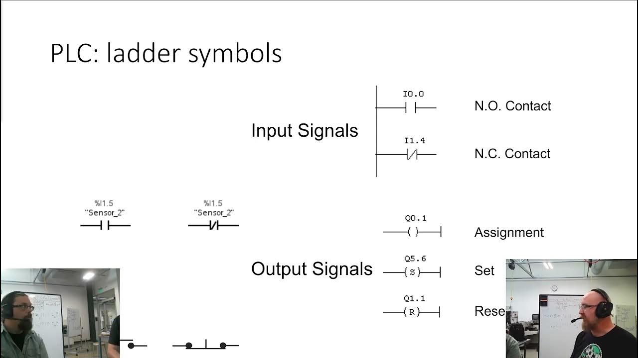
- 😀 The PLC program for Task 1 uses contacts linked to addresses 0.00 (Start) and 0.01 (Stop), controlling an internal holding circuit.
- 😀 The internal holding circuit is named 'H' and ensures the lamp stays on after the start button is pressed.
- 😀 The lamp control is completed by linking the internal address 'H' to the lamp coil at address 100.04 in the program.
- 😀 The program transfer to the PLC is confirmed when the green line appears in the TX programmer, indicating correct connections.
- 😀 In Task 2, the lamp is replaced by a double-acting cylinder, and a solenoid valve is used to control its movement.
- 😀 The solenoid valve is connected to the double-acting cylinder with one electrical socket on each side for forward and reverse motion.
- 😀 The PLC program in Task 2 requires modification to control the air supply and reverse the cylinder's movement using buttons.
- 😀 Testing of both tasks involves ensuring the correct operation of the start/stop button for the lamp in Task 1 and the cylinder in Task 2.
Q & A
What is the main objective of the 9.1 practicum?
-The main objective of the 9.1 practicum is to teach students how to install and transfer PLC programs, focusing on creating a simple lamp control system and then modifying it to control a double-acting cylinder.
What components are used in the schematic drawing for the first PLC program?
-The components used in the schematic drawing for the first PLC program are a 24-volt battery, a start button, a stop button, and a lamp. These components are connected in a series circuit.
What is the purpose of the start and stop buttons in the PLC program?
-The start and stop buttons are used to control the lamp. The start button turns the lamp on, and the stop button turns it off, effectively controlling the on/off state of the lamp in the PLC system.
How are the buttons connected in the PLC wiring?
-The 24V power is connected to the start button, which is then linked to the stop button. The stop button is grounded, and the output is connected to the lamp through a series of PLC address assignments.
What is the significance of address assignments like 0.00 and 1.04 in the PLC program?
-The address assignments like 0.00 (for the start button) and 1.04 (for the lamp output) are used to define the specific inputs and outputs in the PLC system. These addresses tell the PLC where to connect the physical components in the program.
What does the term 'indirect control' mean in the context of this PLC program?
-Indirect control in this PLC program refers to the use of a holding circuit, where a contact (10.00) is used to maintain the state of the lamp, allowing it to remain on or off even if the start/stop buttons are released.
What is the function of the rung in the ladder diagram for the PLC program?
-The rung in the ladder diagram represents a logical condition in the PLC. In this case, it connects the start button, stop button, and output coil (for the lamp) to control the lamp's on/off state.
How is the PLC program verified for correctness before transferring it to the PLC?
-The PLC program is verified by checking for green lines in the ladder diagram. Green lines indicate that there are no errors in the program, and the circuit is complete and functional.
What changes are made for Question 2 of the practicum involving the double-acting cylinder?
-For Question 2, the system is modified to control a double-acting cylinder. A solenoid valve is added to control the cylinder's movement, with the PLC programming updated to trigger the movement of the cylinder using a reverse valve and solenoid activation.
How is the double-acting cylinder controlled within the PLC system?
-The double-acting cylinder is controlled through the solenoid valve connected to the PLC. The program triggers the reverse valve to control the cylinder's motion in both directions, turning off the lamp and using air control during the process.
Outlines

此内容仅限付费用户访问。 请升级后访问。
立即升级Mindmap

此内容仅限付费用户访问。 请升级后访问。
立即升级Keywords

此内容仅限付费用户访问。 请升级后访问。
立即升级Highlights

此内容仅限付费用户访问。 请升级后访问。
立即升级Transcripts

此内容仅限付费用户访问。 请升级后访问。
立即升级浏览更多相关视频
SysAp 7 1 Ladder Logic

1. Tutorial Pemrograman Sekuensial pada PLC
PLC Basics | Programmable Logic Controller

Pressure Sensor, Transducer, and Transmitter Explained | Application of Each

DISTRIBUTE CONTROL SYSTEM (DCS) SISTEM KONTROL TERDISTRIBUSI - DALAM OTOMASI INDUSTRI

PEMROGRAMAN PLC UNTUK OTOMASI INDUSTRI
5.0 / 5 (0 votes)
