Potentiometer Analog Input With Arduino in Tinkercad
Summary
TLDRIn this tutorial, users will learn how to use an Arduino to read a potentiometer and control the flashing rate of an LED. The lesson covers building the circuit, including connecting the potentiometer and LED to the Arduino, and writing simple code to adjust the LED’s behavior based on the potentiometer's position. By reading analog input from the potentiometer, the program adjusts the LED's blinking rate, providing an introduction to Arduino’s analog-to-digital conversion. The tutorial is ideal for beginners, with step-by-step instructions and clear explanations of key concepts like analog input, delay control, and Arduino code structure.
Takeaways
- 😀 Learn how to read a variable resistor, such as a potentiometer, using Arduino’s analog input.
- 😀 Build a simple circuit to control the rate of an LED flash based on the potentiometer's position.
- 😀 Tinkercad Circuits is available for virtual circuit-building, or you can use a physical Arduino Uno and components.
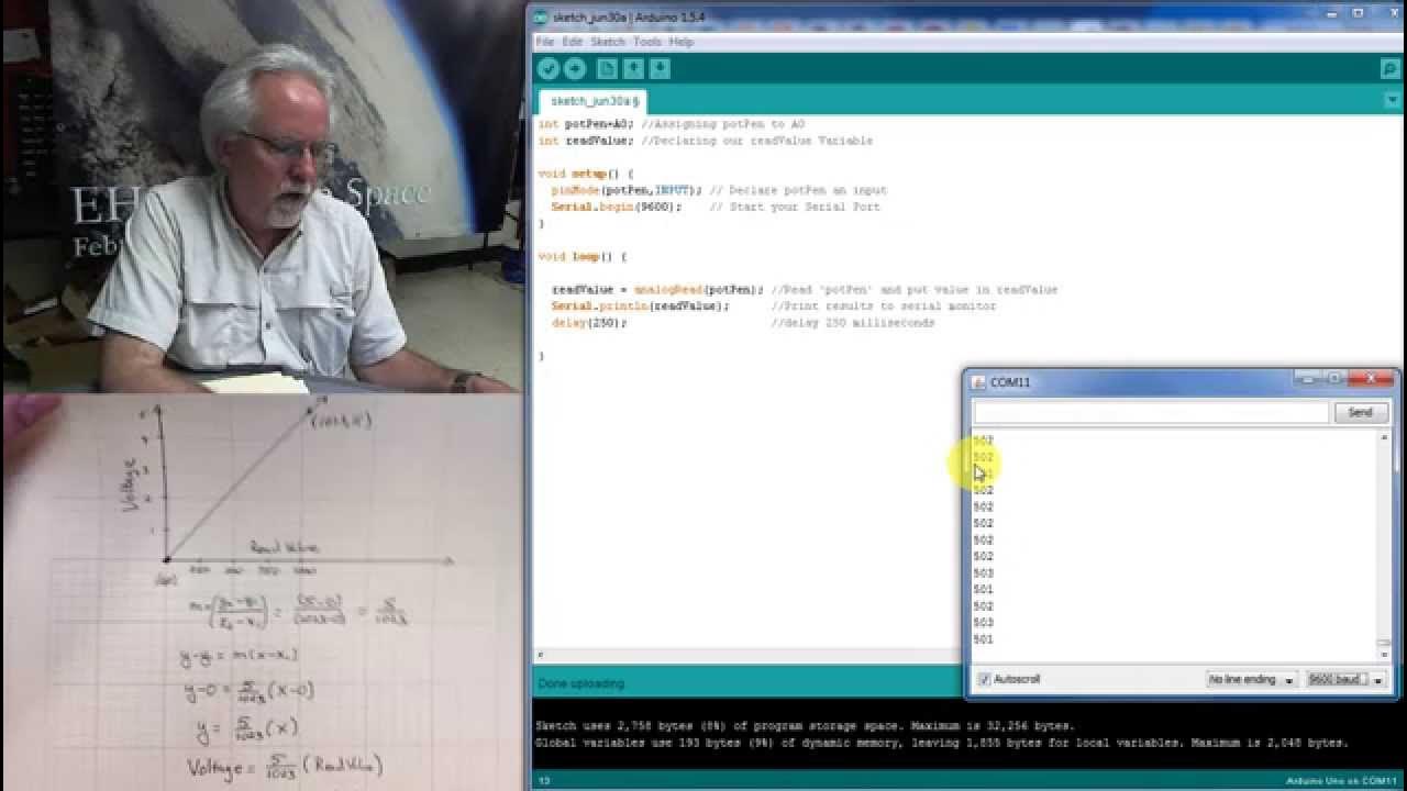
- 😀 The analog input on the Arduino converts a voltage range from 0V to 5V into values from 0-1023 via its ADC (Analog-to-Digital Converter).
- 😀 The potentiometer’s position is mapped to an analog signal, and the Arduino reads it to control LED behavior.
- 😀 Basic components required for the circuit include a potentiometer, LED, resistor, breadboard, and Arduino.
- 😀 The LED flashing rate changes based on the potentiometer value, with delay times ranging from 0 to 1023 milliseconds.
- 😀 A simple code is created to read the potentiometer value using `analogRead()` and control the LED using `digitalWrite()` and `delay()`.
- 😀 You can use either a virtual or physical breadboard setup to wire the components, with the center pin of the potentiometer connected to Arduino pin A0.
- 😀 Learn how to expand this project by integrating the serial monitor to detect sensor data like light, temperature, or distance.
- 😀 For physical builds, copy the generated code from Tinkercad and upload it to your Arduino to run the program on real hardware.
Q & A
What is the purpose of using a potentiometer in this Arduino project?
-The potentiometer is used to control the rate at which an LED flashes based on the knob's position, allowing you to adjust the flashing speed in real-time.
What is the range of values that the Arduino's analog-to-digital converter (ADC) can output?
-The Arduino's ADC converts an incoming analog signal between 0V and 5V into a range of numbers from 0 to 1023.
What does the analogRead() function do in this project?
-The analogRead() function reads the voltage level from the potentiometer connected to pin A0 and returns a corresponding value between 0 and 1023.
How does the value from the potentiometer affect the LED's flashing speed?
-The value read from the potentiometer is used to determine the delay time between turning the LED on and off, meaning the LED flashes faster or slower depending on the knob's position.
What function is used to turn the LED on and off in the Arduino code?
-The digitalWrite() function is used to control the LED by setting it HIGH (on) or LOW (off).
What is the purpose of the delay() function in this project?
-The delay() function pauses the program for a specified amount of time, which in this case is determined by the value read from the potentiometer.
How can you simulate this project virtually?
-You can use Tinkercad Circuits to simulate the project by adding the potentiometer, LED, and Arduino components, and running the code in the virtual environment.
How does the serial monitor contribute to learning in this project?
-The serial monitor helps you visualize the values being read from the potentiometer, providing a way to monitor the analog input in real-time, which is useful for debugging and understanding the readings.
What does the 'sensorValue' variable represent in the code?
-'sensorValue' holds the analog value read from the potentiometer, which is then used to control the delay time for flashing the LED.
What is the advantage of using a breadboard for this project?
-Using a breadboard allows you to easily wire up and modify the circuit components without soldering, making it a flexible and reusable solution for building and testing circuits.
Outlines

此内容仅限付费用户访问。 请升级后访问。
立即升级Mindmap

此内容仅限付费用户访问。 请升级后访问。
立即升级Keywords

此内容仅限付费用户访问。 请升级后访问。
立即升级Highlights

此内容仅限付费用户访问。 请升级后访问。
立即升级Transcripts

此内容仅限付费用户访问。 请升级后访问。
立即升级浏览更多相关视频

Part 4: Belajar Menggunakan ADC Arduino untuk Membaca Data Sensor dengan Mudah

Como usar PINO DIGITAL de ENTRADA no arduino - Curso Gratuito pelo Tinkercad - Aula 2

Arduino Analog Inputs

Pushbutton Digital Input With Arduino in Tinkercad

LESSON 10: Reading Analog Voltages with Arduino

SIMULASI WOKWI MENGUANKAN BLYNK ARDUINO
5.0 / 5 (0 votes)
