Rangkaian RLC Seri
Summary
TLDRIn this lecture, the speaker explores the fundamentals of series RLC circuits, emphasizing their importance in electronics, particularly in tuning circuits and filters. The discussion covers the interaction between resistors, inductors, and capacitors, focusing on AC signal responses, impedance, and resonance frequency. The speaker explains how inductive and capacitive reactances influence circuit behavior, highlighting that at resonance, impedance equals resistance, maximizing current flow. A practical example illustrates the calculation of resonance frequency, reinforcing key concepts. The session concludes with a recap of the main points, encouraging viewers to subscribe for future updates.
Takeaways
- 😀 RLC series circuits consist of a resistor, inductor, and capacitor connected in series.
- 🔊 These circuits are commonly used in applications like radio tuning and band-pass filters.
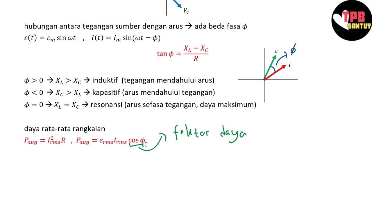
- ⚡ The resonant frequency occurs when the inductive reactance equals the capacitive reactance.
- 📉 At resonant frequency, the total impedance of the circuit is equal to the resistance (Z = R).
- 💡 The formula for calculating resonant frequency is f = 1 / (2π√(LC)).
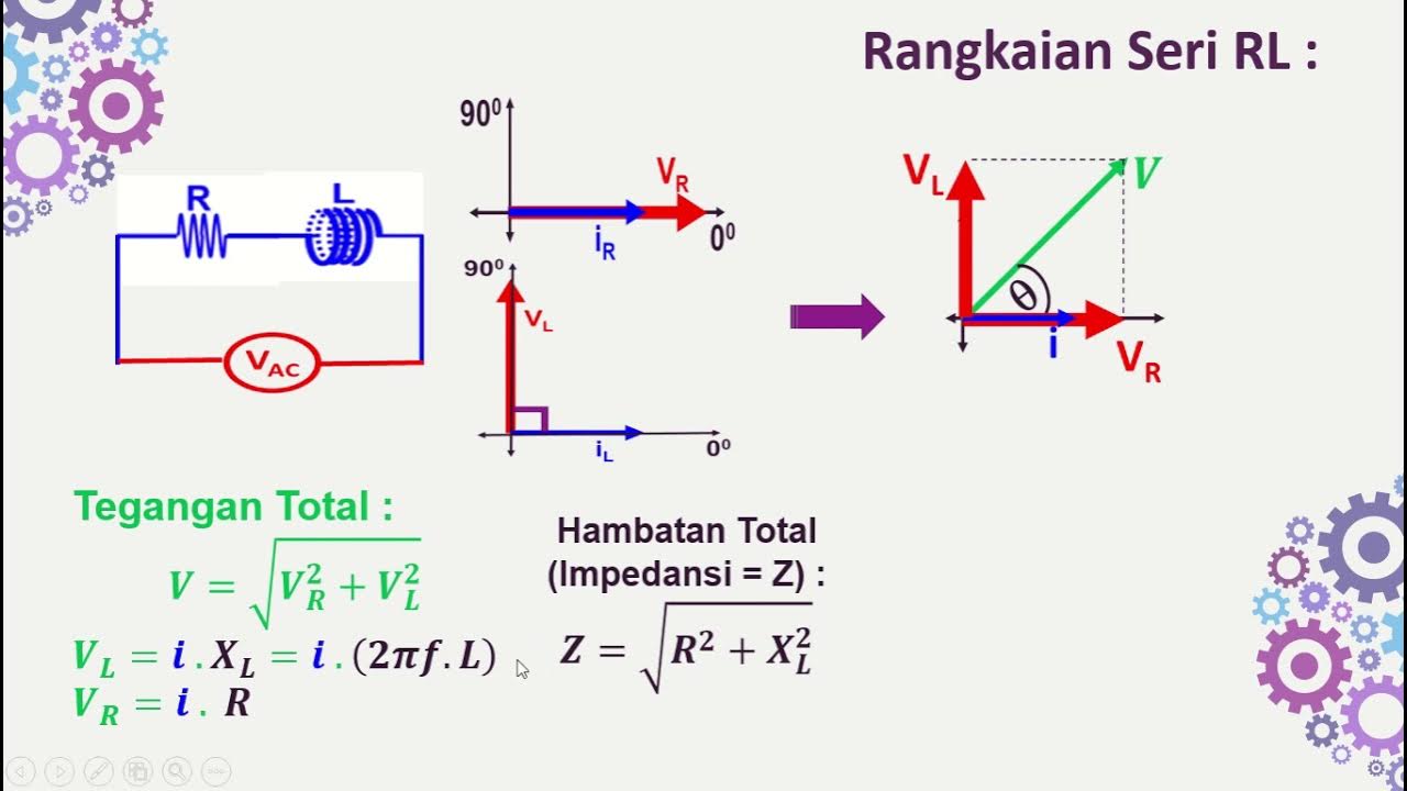
- 🧮 Inductors create a phase shift where voltage leads current by 90 degrees, while capacitors cause voltage to lag by 90 degrees.
- 📊 Impedance is a complex quantity that combines resistance and reactance in AC circuits.
- 🌊 At resonance, current reaches its maximum value since impedance is at its minimum.
- 📈 Understanding the behavior of RLC circuits is essential for efficient electronic circuit design.
- 🙋♂️ The lecture encourages viewers to engage by asking questions and subscribing for future content updates.
Q & A
What is the main topic discussed in the video?
-The video discusses the series RLC circuit, focusing on its principles, applications, and response to AC signals.
What components make up a series RLC circuit?
-A series RLC circuit is composed of a resistor, an inductor, and a capacitor connected in series with a voltage source.
How does resonance occur in an RLC circuit?
-Resonance occurs when the inductive reactance equals the capacitive reactance, resulting in the impedance of the circuit being equal to the resistance alone.
What is the significance of the frequency at which resonance occurs?
-At the resonant frequency, the circuit allows maximum current to flow, and the power is at its highest due to the impedance being purely resistive.
What is the formula for calculating resonant frequency in an RLC circuit?
-The resonant frequency (F) can be calculated using the formula F = 1 / (2π√(LC)), where L is the inductance and C is the capacitance.
How does the behavior of current and voltage differ in an RLC circuit?
-In an RLC circuit, the current remains constant throughout the components, while the voltage can change, especially across the inductor and capacitor depending on the frequency.
What happens to the phase relationship between voltage and current in an inductor?
-In an inductor, the voltage leads the current by 90 degrees, indicating a phase delay in current flow.
What is the role of the resistor in an RLC circuit?
-The resistor causes a linear voltage drop proportional to the current flowing through the circuit, contributing to the overall impedance.
How do you derive the total impedance in a series RLC circuit?
-The total impedance is calculated by combining the resistive and reactive components, with the formula Z = R + j(XL - XC), where XL is the inductive reactance and XC is the capacitive reactance.
What are some practical applications of series RLC circuits?
-Series RLC circuits are commonly used in tuning circuits for selecting desired radio frequencies, as bandpass filters, and as signal generators producing sinusoidal waves.
Outlines

此内容仅限付费用户访问。 请升级后访问。
立即升级Mindmap

此内容仅限付费用户访问。 请升级后访问。
立即升级Keywords

此内容仅限付费用户访问。 请升级后访问。
立即升级Highlights

此内容仅限付费用户访问。 请升级后访问。
立即升级Transcripts

此内容仅限付费用户访问。 请升级后访问。
立即升级5.0 / 5 (0 votes)


