Part Modeling - Create Construction Planes and Axes

Craig Hughes
30 Apr 202208:07

Summary

TLDRThis video covers key objectives for the Autodesk Fusion 360 Certified User Exam, focusing on part modeling, specifically the creation of construction planes and axes. The tutorial explains how to create various types of construction geometry, such as offset planes, angled planes, midplanes, and tangent planes. It also demonstrates the creation of axes using different methods, including through cylinders or between two points. Practical examples are provided to guide users in building complex geometries. The video emphasizes practice to ensure success in the exam and offers tips on editing and managing construction geometries within Fusion 360.

Takeaways

  • 🔧 The video covers part modeling in Autodesk Fusion 360, focusing on creating construction planes and axes.
  • 📐 Construction geometry in Fusion 360 includes planes, axes, and points, with this video focusing on planes and axes for the ACU exam.
  • 🛠️ Offset planes allow you to select a face or plane and create a new plane at a specified distance or offset.
  • 📏 A plane at an angle can be created by selecting an edge or line and specifying an angle, useful for complex geometry setups.
  • 🔄 The mid-plane tool creates a plane between two parallel faces, commonly used for mirroring or patterning geometry.
  • 🎯 Plane through two edges and plane through three points are other options for creating precise construction planes based on existing geometry.
  • 🌀 Tangent planes align to circular faces and can be adjusted to be tangent at different angles or positions.
  • 📊 Axis creation includes options like axis through a cylinder, perpendicular at a point, or axis through two planes for precise alignment.
  • 📍 Axis through an edge and axis through two points are simple tools to create axes directly from existing edges or points in the model.
  • 📂 All created construction geometry is organized in a folder in the browser, can be edited or deleted, and is tracked in the model history tree.

Q & A

  • What is the main focus of this video related to Autodesk Fusion 360?

    -The video focuses on part modeling in Autodesk Fusion 360, specifically dealing with creating construction planes and axes, which are essential for preparing for the Autodesk Certified User (ACU) exam.

  • What is a construction plane, and why is it important in Autodesk Fusion 360?

    -A construction plane in Autodesk Fusion 360 provides a flat surface where users can create sketches. It allows the creation of more complex geometry by serving as a reference for sketches and design modifications.

  • How do you create an offset plane in Fusion 360?

    -To create an offset plane, you can either choose one of the principal work planes or select a face and offset it by a certain distance. You can type in a number or drag the offset, and you can also reference another object for the offset.

  • What is a 'plane at an angle,' and how do you create it?

    -A 'plane at an angle' is a work plane created at a specific angle from a line. You select a line (like an edge) and set the angle, allowing you to sketch geometry that will come off that angle, such as at 45 degrees.

  • How does the 'mid plane' option work in Fusion 360?

    -The mid plane option allows you to select two faces, and it creates a work plane exactly in the middle of those two faces. This can be useful for mirroring or creating symmetrical designs.

  • What is the 'plane through two edges' feature, and how does it function?

    -The 'plane through two edges' feature allows you to select two edges, and Fusion 360 will create a work plane that passes through both selected edges, which is helpful for sketching or aligning geometry.

  • Can you explain the 'axis through a cylinder' feature?

    -The 'axis through a cylinder' feature creates an axis line directly through the center of a cylindrical object, helping define rotational symmetry or allowing for further construction geometry.

  • How do you create an axis perpendicular to a point in Fusion 360?

    -To create an axis perpendicular to a point, you select a point on a face. Fusion 360 will generate an axis that is perpendicular to the selected point, which can be useful for precise alignment.

  • What does the 'axis through two planes' option achieve?

    -The 'axis through two planes' option creates an axis at the intersection of two selected planes. This can help define the axis for rotational geometry or other alignment needs.

  • How does Fusion 360 manage and track construction geometries?

    -When you create construction geometries (such as a tangent plane), they are stored in a folder in the browser and also appear in the model history tree. These elements can be edited or deleted, and changes can be tracked throughout the modeling process.

Outlines

00:00

🛠️ Introduction to Fusion 360's Construction Geometry Tools

This paragraph introduces the Autodesk Fusion 360 Certified User Exam objective, focusing on the 'Part Modeling' section, specifically the use of construction planes and axes. The video will cover these tools to help users prepare for the exam, particularly the sections on creating construction geometry. The section starts with creating an offset plane, which allows users to select a plane or face and define its offset at a specific distance. This section sets the stage for more complex geometry creation using various construction tools.

05:01

📏 Creating and Using Work Planes in Fusion 360

The focus here is on various types of work planes in Fusion 360, including offset planes, planes at an angle, and tangent planes. The explanation includes how to create and manipulate these planes for sketching complex geometries. It covers the practical uses of each, such as placing a plane at a 45-degree angle along an edge or setting a tangent plane on a circular object. The paragraph highlights how these work planes serve as surfaces for sketching and setting up more advanced shapes in a 3D model.

🔄 Midplane and Other Advanced Plane Techniques

This paragraph explores advanced plane creation techniques like midplane, which places a plane equidistant between two selected faces. It also introduces the 'Plane through Two Edges' and 'Plane through Three Points' methods, which help create planes by selecting multiple edges or points. These tools are useful for more precise and symmetrical modeling. There is also a brief mention of planes tangent to a face at a point, though this is less common in practice.

🛤️ Using Planes Along a Path

This section discusses the technique of creating a plane along a path, where users can follow a selected edge or curve to set a plane that is perpendicular to it. The process involves selecting the path, and the plane adjusts to fit the path’s position. This tool helps create planes that follow more intricate model details, such as edges of cylinders, adding flexibility to design processes that require precise alignment along specific model features.

🔧 Working with Axes in Fusion 360

This paragraph shifts the focus to creating and managing axes. The first method demonstrated is creating an axis through a cylinder, cone, or torus, which automatically places an axis through the object’s center. The author provides a step-by-step guide for deleting unnecessary planes to focus solely on axis creation. These techniques help define center points and alignments within cylindrical or rounded parts of the model.

📐 Creating Axes Perpendicular to Points and Between Planes

Here, the author explains how to create axes perpendicular to a selected point on a face or surface. It also covers how to place axes where two planes intersect. These methods allow for greater control in defining exact points and lines in the model, helping to improve precision in the construction geometry. Examples are given, including how to select specific points or faces for enhanced accuracy during modeling.

🔀 Axis Creation Through Two Points and Along Edges

The paragraph discusses additional axis creation techniques, including axes that run through two points (e.g., the corners of a model) and axes along selected edges. These options resemble drawing a line between two points or edges in 3D space, further extending the flexibility of construction geometry tools. These techniques are useful when modeling complex parts requiring exact symmetry or alignment.

🧭 Managing Construction Geometry and Exam Preparation Tips

This final section offers a reminder that all construction geometries, such as tangent planes, are saved in a dedicated folder in the browser tree. Users can edit or delete them, and the history is tracked in the model tree for future adjustments. The paragraph concludes with a message encouraging viewers to keep practicing for the Autodesk Certified User Exam, emphasizing the importance of mastering these tools to ensure success on the first attempt.

Mindmap

Keywords

💡Construction Geometry

Construction geometry refers to auxiliary geometric elements such as planes, axes, and points that assist in defining complex shapes or features within a 3D model. In Fusion 360, these elements do not appear in the final design but are crucial for positioning and creating sketches or features. The video highlights several construction geometries like offset planes, mid planes, and axes that help in building precise models.

💡Offset Plane

An offset plane is a work plane created at a specified distance from an existing plane or face. In the video, the instructor demonstrates how to create an offset plane by selecting a principal work plane or a face, and then setting a distance for the plane to be positioned away from the reference. This allows the designer to create features at specific distances from other geometry.

💡Plane at an Angle

A plane at an angle is a construction geometry created at a specified angle relative to a line or edge. The video describes how selecting an edge and specifying an angle, like 45 degrees, allows users to create a plane on which new sketches can be made. This is useful for creating features that are inclined or slanted relative to the main geometry.

💡Mid Plane

A mid plane is a construction plane that is positioned equidistant between two selected faces or surfaces. In the video, the instructor demonstrates how selecting two opposite faces results in a plane positioned at the center between them. This tool is commonly used for symmetry operations, such as mirroring or patterning features evenly across a part.

💡Tangent Plane

A tangent plane is a plane that is positioned tangentially to a curved surface, such as a cylinder. The video illustrates how selecting a cylindrical face automatically places a plane that is tangent to the curve, which can then be used to create features like cuts or sketches that align with the surface. This is useful when working with rounded or circular parts.

💡Axis through Cylinder

An axis through a cylinder is a line or axis automatically placed along the center of a cylindrical or conical object. In the video, the instructor shows how selecting a cylinder creates an axis right through its center. This is a crucial reference for rotational symmetry and for aligning parts or features along a central axis.

💡Axis Perpendicular at a Point

This construction axis is created perpendicular to a surface at a specific point. The video explains how this axis is generated when a user selects a point on a face. While it’s not as commonly used as other construction geometry, it can be important in ensuring precision when dealing with non-orthogonal surfaces or for specific modeling operations like split bodies.

💡Plane through Two Edges

A plane through two edges is a construction geometry created by selecting two edges, which results in a plane passing through both. This tool allows for more complex plane creation when dealing with irregular geometry. In the video, the instructor shows how selecting different edges produces varying planes, depending on the orientation of the edges.

💡Plane through Three Points

A plane through three points is a plane that is defined by selecting three distinct points in space. In the video, the instructor illustrates this by choosing corner points on a part, and the plane is automatically positioned to pass through all three points. This method allows precise control when working with non-planar surfaces or custom constructions.

💡Axis through Two Points

An axis through two points is a line created between two selected points, similar to drawing a line between them. In the video, the instructor demonstrates how selecting two corners of the model results in an axis being created between those points. This tool is helpful for referencing and aligning features when the geometry of the model doesn’t provide an existing edge or axis.

Highlights

Introduction to Autodesk Fusion 360 Certified User Exam, focusing on the part modeling section and creating construction planes and axes.

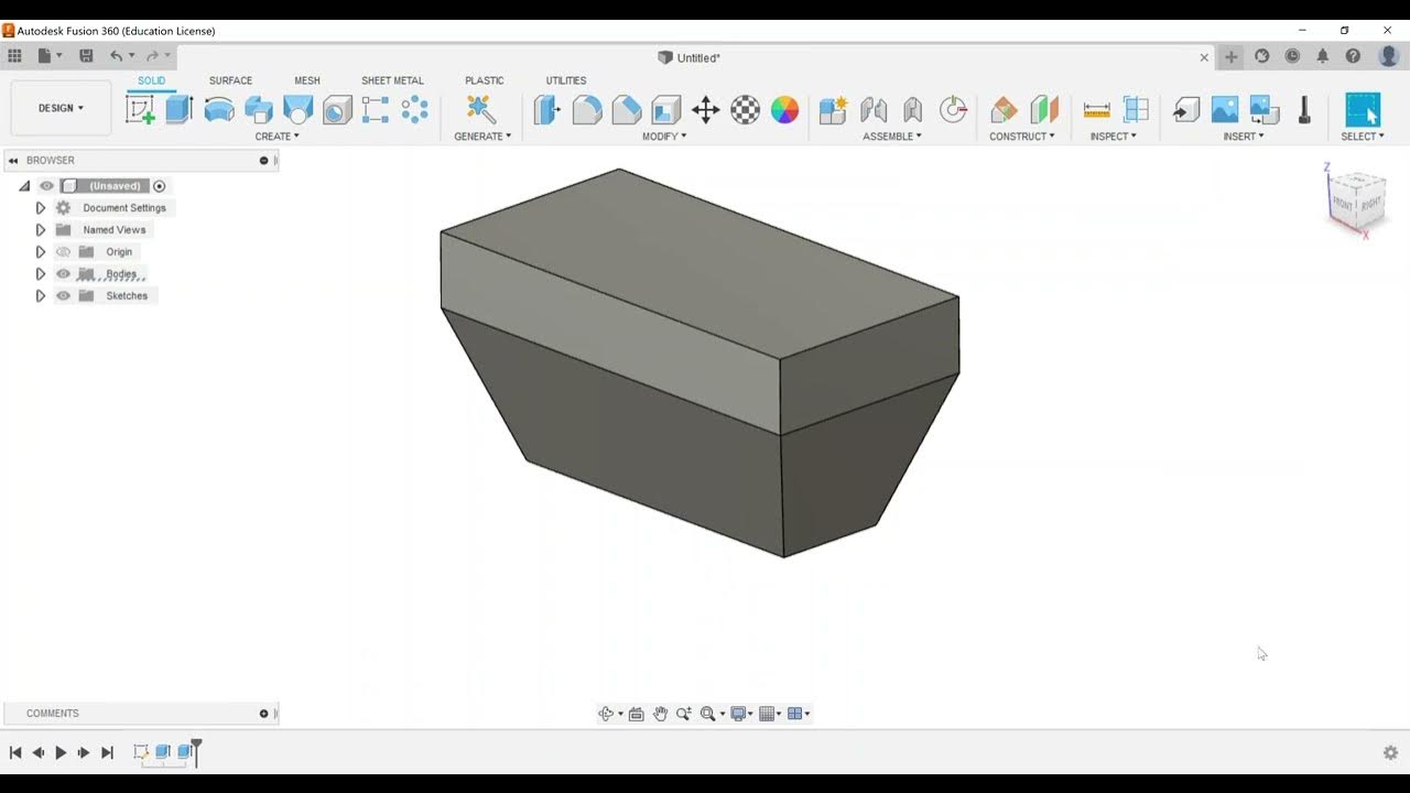
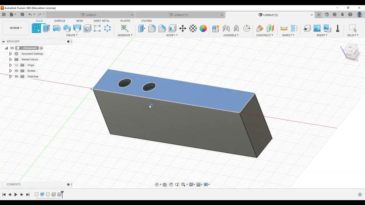
Overview of construction geometry in Fusion 360, demonstrated with a simple part created for practice.

Detailed explanation of the 'Offset Plane' tool, including its ability to select a face and set it at a specific distance.

Explanation of 'Plane at an Angle' by selecting an edge and setting an angular plane, useful for creating sketches on different angles.

Demonstration of 'Tangent Plane' creation, highlighting how to set a plane tangent to a circular face and adjust its angle.

Discussion on 'Mid Plane,' which places a work plane between two faces, useful for symmetrical design and mirroring.

Explanation of 'Plane through Two Edges,' using selected lines to create a work plane between them.

Demonstration of 'Plane through Three Points,' showcasing how selecting three points forms a plane at their intersection.

Introduction to the 'Axis through Cylinder or Cone,' showing how to place an axis directly through the center of a cylindrical object.

Explanation of 'Axis Perpendicular at a Point,' describing how it works better when a precise point is used.

Demonstration of 'Axis through Two Planes,' placing an axis where two selected planes intersect.

Explanation of 'Axis through Two Points,' which creates an axis between two selected points like drawing a line.

Discussion on the ease of creating an axis through an edge, with an example of placing one along a selected edge.

Explanation of 'Axis Perpendicular to Face at a Point,' using a face and point selection to place an axis at that point.

Final tip on managing construction geometry within the Fusion 360 browser, including editing and deleting construction elements.

Transcripts

play00:01

hey there everyone again we're going to

play00:03

be looking at another autodesk fusion

play00:05

360 certified user exam objective

play00:08

and with that we're going to take a look

play00:10

at our part part modeling section

play00:13

which is going to be dealing with

play00:14

creating construction planes

play00:17

and axes so here in fusion i have a part

play00:21

created

play00:22

so called construction geometry and so

play00:24

this is kind of a very basic part that i

play00:26

used to practice with

play00:28

creating construction geometry so we're

play00:30

going to be working with

play00:31

mainly you got a few sections here you

play00:33

got one that deals with planes at the

play00:35

top you got a second section it all

play00:37

deals with axes or creating an axis

play00:40

and then the third section is creating

play00:42

points so the acu exam only covers the

play00:46

first two sections so that's all that

play00:48

this video is going to cover so i'm

play00:49

going to kind of work our way down just

play00:51

kind of creating a lot of the

play00:52

construction geometries the first one is

play00:55

going to be an offset

play00:57

plane offset plane is pretty easy you

play00:59

can either choose one of the principal

play01:01

work planes or

play01:03

you can select a face

play01:05

and then set it offset at a certain

play01:07

distance

play01:08

away

play01:09

from there and then either you can click

play01:11

and drag or you can type in

play01:13

a number or you could also say to an

play01:15

object as well and then select it right

play01:17

now i don't have any really objects

play01:19

honestly other than this other point

play01:21

down here that i'm picking up but allows

play01:23

me to go through and offset from that

play01:24

but again a distance

play01:26

is what we have for an offset plane

play01:28

going through the next one playing at an

play01:30

angle if i select for example

play01:33

the

play01:34

edge it's looking for a line so if i

play01:36

select this top line i can set a plane

play01:39

at let's say 45 degrees and then have it

play01:42

be uh where i can then create a sketch

play01:46

on the work plane and be able to draw

play01:48

something and have it come off of there

play01:50

so that's really what all these work

play01:52

planes are used for is how to be able to

play01:54

create more complicated geometry and set

play01:56

up sketch

play01:58

a surface for the sketch to be placed on

play02:00

tangent plane is pretty easy so if you

play02:03

select a face of a circular object

play02:05

it's going to set as i click and drag

play02:07

the grip

play02:08

it stays tangent

play02:10

to the face of the cylinder that i have

play02:12

here so and i can set it at a different

play02:15

angle or a different position that i

play02:17

need

play02:19

mid plane is a pretty easy object so

play02:22

what it does is that for example if i

play02:24

choose like this side and then if i

play02:26

choose this face it's going to put a

play02:28

work plane right down the center between

play02:31

right in the middle of the two faces

play02:33

that i select so

play02:35

mid plane just goes through and puts

play02:37

that in there which can be very

play02:38

beneficial

play02:40

you can also use it for some mirroring

play02:42

and some patterning options as well

play02:44

so as we go through plane through two

play02:46

edges so here i'll select this edge and

play02:49

i'll select this edge and that's going

play02:51

to create a plane right there at where

play02:54

are those two lines that i selected if i

play02:56

hit the x i can always go through and

play02:58

choose like maybe this one and this one

play03:00

and you can see what kind of effect that

play03:02

it has

play03:04

playing through three points if i choose

play03:06

the points which are like the corners i

play03:09

can choose this one and this one and

play03:10

then this one and now we'll go through

play03:12

and do the same kind of thing so this

play03:14

plane is going to be

play03:15

touching right at those points

play03:20

playing that's tangent to a face at a

play03:22

point so here it kind of tells me what

play03:24

to do so here it's not as common but if

play03:27

you select your

play03:29

cylindrical face i'm going to select at

play03:31

this point

play03:32

it's going to go and put that again

play03:33

tangent to the face and it's going to be

play03:36

following that point as well so again

play03:39

this one's not near as common of a

play03:40

construction geometry but can be used

play03:43

on kind of they were saying in the tool

play03:45

tip

play03:46

it can be used for

play03:48

modeling tools like split body and

play03:50

things like that

play03:52

the last one here is playing along a

play03:54

path so when you select it here's what

play03:56

i'll do is i like to go through and when

play03:59

you start to it says to choose the path

play04:01

and we have a tangent chain so i'm going

play04:03

to select this edge here

play04:05

now it's going to follow along the edge

play04:07

and it has certain points it's picked up

play04:09

so if i hit cancel i'm going to try that

play04:11

one more time

play04:12

so here's where we go through and we can

play04:14

get like for example here's our cylinder

play04:17

so we can go through and set a plane and

play04:19

you can see where it kind of starts and

play04:21

stops

play04:23

and that's just some of the some of the

play04:25

things that you can do with a plane

play04:27

along a path

play04:29

as you go along and you can select what

play04:30

edge or face

play04:33

and it's going to follow that line and

play04:36

put that plane kind of perpendicular to

play04:37

the line so

play04:39

all right so that covers all the planes

play04:41

now we're going to look at the axes so

play04:43

the axis first one here is accessed

play04:46

through a cylinder cone or taurus so if

play04:48

i just choose a cylinder it's going to

play04:50

put a it's going to put an axis right

play04:52

down through the center it's going to

play04:53

find the direct center and put an axis

play04:55

through there so i'm going to go ahead

play04:56

and i'm going to delete this

play04:59

plane and i'm going to delete this one

play05:01

as well

play05:02

so

play05:02

i'm going to go ahead and choose the

play05:03

next option axis perpendicular at a

play05:06

point so if we had a point on our face

play05:09

here wherever we click

play05:11

it's going to set a or if you click

play05:13

somewhere it's not as precise

play05:16

unless you have a point there so points

play05:18

can be used quite a bit

play05:22

and uh

play05:24

you know that kind of helps with some of

play05:25

the

play05:26

the accuracy there again not quite as

play05:29

common

play05:32

access to two planes

play05:34

so i can choose like maybe here and here

play05:37

and that's going to put an axis where

play05:38

those are connected again just to kind

play05:40

of show that off if i go through and use

play05:43

like for example even this and

play05:45

i need something that's kind of

play05:47

perpendicular i can choose these two

play05:48

it's going to put an axis right at the

play05:50

edge where those two planes meet

play05:54

i can do an axis through two points so

play05:56

like here if i click the corners go down

play05:58

to down it's going to put an axis right

play06:00

down where those are connected

play06:02

kinda like drawing a line

play06:04

axis through an edge that one's pretty

play06:06

easy i can choose an edge like this put

play06:08

an axis right there

play06:12

and then the last one accent axis

play06:14

perpendicular to face at a point so

play06:16

again i can choose like this one and if

play06:18

i choose the point for the origin it'll

play06:20

put it right at the point so i select

play06:22

the face and it puts it right at that

play06:24

point

play06:25

that we have there so again a lot of

play06:28

different ways that you can get

play06:30

different construction geometries and

play06:32

some may look like they even had the

play06:34

same kind of effect and it depends on

play06:36

how complex your part is this one here

play06:38

is just a really good example that i

play06:40

used to show how to create a lot of the

play06:42

very common construction

play06:44

geometry

play06:45

kind of elements that we have so the

play06:48

last thing i'll leave you with is

play06:49

anytime you create

play06:51

for example a

play06:53

a can any construction geometries like a

play06:55

tangent plane

play06:57

i'll go ahead and set one here you will

play06:59

gain a folder in your browser and then

play07:02

you'll also notice it will show up in

play07:04

your model history tree so it is

play07:06

something that can be edited and when

play07:07

you right click and choose edit feature

play07:09

you can go through and make changes and

play07:12

and change like the reference plane or

play07:14

anything like that but

play07:16

that is something that can be edited and

play07:19

be

play07:19

tracked in your browser

play07:21

in your model history tree as you go

play07:23

through and are modeling the different

play07:25

parts so

play07:27

it can also be something that can be

play07:28

deleted so that's what i'll do and then

play07:31

once i lose that construction geometry

play07:34

that folder goes away so

play07:36

all right this video concludes on how to

play07:38

create construction geometries

play07:40

within fusion 360 for the autodesk

play07:43

certified user

play07:45

exam

play07:46

and

play07:48

again continue to practice continue to

play07:50

study the goal of this is to make you

play07:52

successful on the first attempt so if

play07:54

you have questions contact me

play07:56

but in the meantime continue to look

play07:58

through some of the videos spotlighting

play08:00

other autodesk fusion 360

play08:03

exam objectives

Rate This

5.0 / 5 (0 votes)

相关标签
Autodesk Fusion 360Construction geometryCertified user examPart modelingPlanes and axesOffset planesTangent planeSketching surfacesAxis creation3D modeling
您是否需要英文摘要?