RC snubber circuit design and calculations for inductive loads
Summary
TLDRThis video explains how to use a Narcisse Nova network to reduce transient voltages across switches, protecting them from voltage spikes in circuits with inductive loads like solenoids. The video demonstrates the issue of high voltage spikes when a switch is opened, showing how a snubber network (resistor and capacitor) can absorb the energy and limit transient voltage to safe levels. Through detailed calculations, the video provides a step-by-step guide for selecting appropriate resistor and capacitor values, ultimately helping users implement this solution to protect switches and relays in their circuits.
Takeaways
- 😀 Snubber networks, like Narcisse Nova, are used to reduce transient voltages across switches and protect them from voltage spikes when the switch opens.
- 😀 These voltage spikes occur when circuits contain inductive loads, such as solenoids, which can cause high transient voltages that may damage switches and relays.
- 😀 When a switch is opened in a circuit with an inductive load, the inductor attempts to maintain current flow by increasing the voltage across the switch, causing a transient voltage.
- 😀 The transient voltage can reach significantly higher values than the supply voltage, even in the kilovolt range, which may result in sparking and switch failure.
- 😀 A simulation demonstrates that without snubber protection, transient voltages can spike to over 5.5 kilovolts when the switch opens in an inductive load circuit.
- 😀 If the circuit were resistive rather than inductive, there wouldn't be any transient voltage spikes, as there's no energy stored in an inductor to maintain current flow.
- 😀 A properly designed snubber network absorbs the energy stored in the inductor, limiting the voltage rise across the switch to a safer level, for example, 50 volts DC.
- 😀 Using a snubber network with a resistor and capacitor allows us to effectively limit the transient voltage spikes and ensure the switch operates within safe voltage limits.
- 😀 The calculation of appropriate values for the snubber network resistor (R) and capacitor (C) is essential to ensure the transient voltage is controlled and does not exceed the switch's voltage rating.
- 😀 The video outlines how to calculate the resistor and capacitor values based on energy stored in the inductor, the desired maximum voltage, and the current flowing through the circuit, using formulas for inductive energy and capacitive energy storage.
Q & A
What is the main purpose of using a Narcisse Nova network in electrical circuits?
-The main purpose is to reduce transient voltages across switches to acceptable levels, protecting switches and relays from voltage spikes, especially when the switch is open.
Why is a snubber network needed in circuits containing inductive loads like solenoids?
-Inductive loads, like solenoids, store energy in their magnetic fields. When the switch is opened, the energy in the inductor causes a transient voltage that can be much higher than the source voltage, potentially leading to sparking and switch damage.
What is the effect of opening the switch in a circuit with an inductive load?
-When the switch is opened, the inductor tries to keep the current flowing by raising the voltage across the switch, resulting in a high transient voltage spike. This can reach kilovolt levels and cause sparking.
How does a snubber network prevent high voltage spikes when the switch is opened?
-The snubber network, which includes a resistor and capacitor, absorbs the energy stored in the inductor, limiting the voltage rise to an acceptable level, thereby preventing excessive voltage spikes across the switch.
How can the appropriate values of the snubber resistor and capacitor be calculated?
-The values can be calculated by considering factors such as the energy stored in the inductor, the desired maximum transient voltage, and the resistance and inductance values in the circuit. Calculations for current, energy, and capacitance are crucial steps in determining the right values.
What is the role of the resistor in the snubber network?
-The resistor in the snubber network limits the current flowing through the coil and helps dissipate energy, preventing excessive voltage rise when the switch is opened.
What formula is used to calculate the energy stored in an inductor?
-The formula for the energy stored in an inductor is: Energy (Joules) = 0.5 × Inductance (L) × Current (I)^2.
How is the required capacitance value for the snubber network determined?
-The required capacitance is calculated using the energy stored in the inductor and the maximum voltage that the capacitor will handle, with the formula: Energy = 0.5 × Capacitance × Voltage^2.
What is the significance of choosing a maximum voltage for the capacitor?
-Choosing a maximum voltage for the capacitor ensures that the transient voltage does not exceed a safe threshold, providing protection for the circuit components. For example, limiting the voltage to 50 volts ensures safety when the switch is rated for 100 volts.
How does the snubber network affect the current when the switch is closed?
-When the switch is closed, the capacitor in the snubber network is charged, and the current flows normally without the snubber having an effect. It only absorbs energy when the switch is opened.
Outlines

This section is available to paid users only. Please upgrade to access this part.
Upgrade NowMindmap

This section is available to paid users only. Please upgrade to access this part.
Upgrade NowKeywords

This section is available to paid users only. Please upgrade to access this part.
Upgrade NowHighlights

This section is available to paid users only. Please upgrade to access this part.
Upgrade NowTranscripts

This section is available to paid users only. Please upgrade to access this part.
Upgrade NowBrowse More Related Video

Kirchhoff's Voltage Law (KVL) Explained

Capacitors and Kirchhoff: Crash Course Physics #31

KVL and KCL Examples (Circuits for Beginners #12)
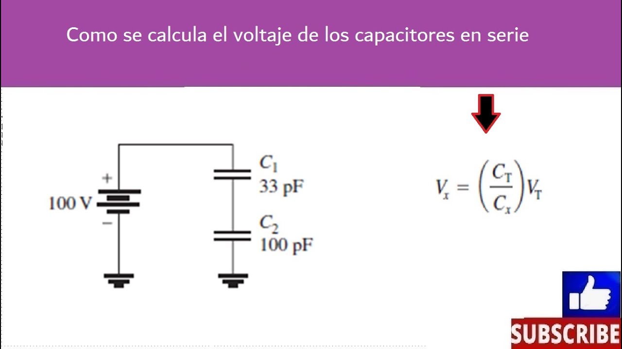
Voltaje de capacitores en serie

TEI3B2 - Elektronika B - Analisis DC BJT - Voltage Divider
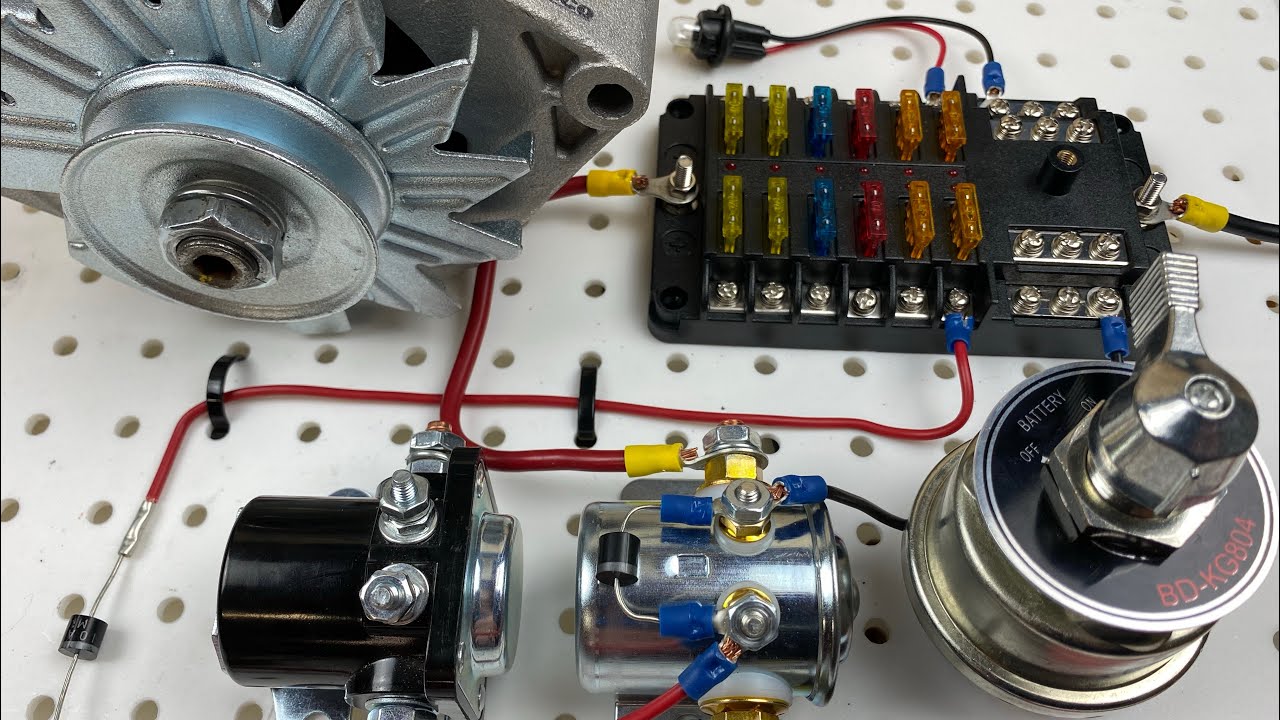
Hotrod | Race car | Drift car Wiring for Beginners. (Alternator Battery Switch Fuse Box Starter)
5.0 / 5 (0 votes)