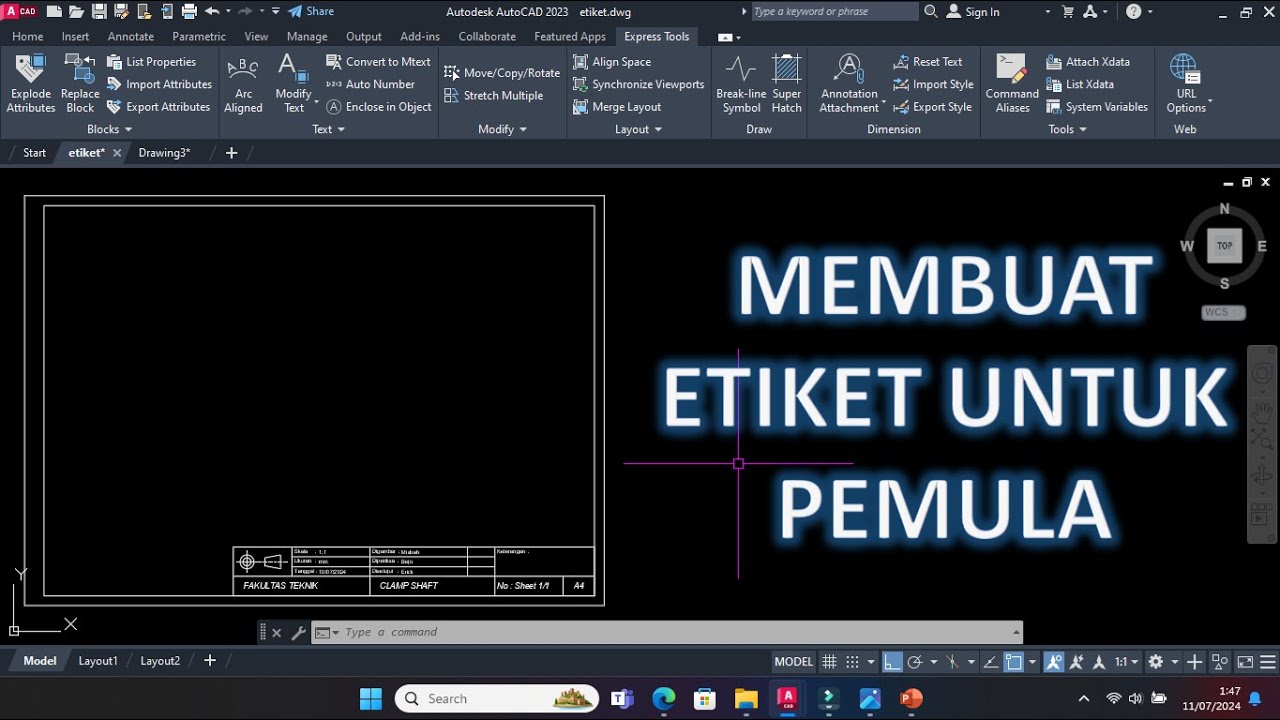
Cara Membuat Garis Tepi dan Etiket Gambar Teknik Kertas A4 di Autodesk AutoCad
Summary
TLDRIn this tutorial, the creator demonstrates how to create an engineering label (etiquette) using Autodesk AutoCAD, specifically for beginners. The video walks through essential steps, starting from setting units in AutoCAD, defining paper size, and creating boundary lines for an A4 sheet. The creator explains how to draw precise lines, configure text labels, and use commands to finalize the design. Additionally, the video includes tips on how to adjust the design for different paper sizes and the importance of adding technical details such as scale and projection types. Aimed at making the process clearer and slower for beginners.
Takeaways
- 😀 Open Autodesk AutoCAD (version 2021) to start the drawing process.
- 😀 Set up drawing units by typing 'UNITS' and choose the desired unit type (mm) and precision (0.00).
- 😀 Configure the paper size by typing 'LIMITS' to set the X and Y axes to A4 dimensions (297mm x 210mm).
- 😀 Use the 'RECTANGLE' command to draw the paper boundary with the specified A4 size.
- 😀 Draw the paper edge lines, ensuring the dimensions are accurate and aligned to the set limits.
- 😀 For a more precise boundary, use commands like 'LINE' and set specific values like 5mm or 20mm for margins.
- 😀 Label the drawing by adding text fields for information like scale (e.g., 1:1) and date.
- 😀 Adjust text positioning and use the 'MOVE' command to align text for better readability.
- 😀 Organize the layout, copy and paste elements as necessary to save time and maintain consistency.
- 😀 Use projection types like American or European for different technical drawing styles and ensure the appropriate one is selected.
Q & A
What is the purpose of setting units in AutoCAD during the tutorial?
-Setting the units in AutoCAD is crucial for defining the measurement system. In the tutorial, the speaker sets the units to millimeters (mm) with decimal precision of 0.00 to ensure accurate and consistent scaling of the drawing.
How do you set the limits for the drawing in AutoCAD?
-To set the drawing limits, type 'limits' in the command line and press Enter. Then, set the X and Y coordinates to the desired values for your paper size (A4 in this case, with an X value of 297 mm and a Y value of 210 mm).
Why is it important to adjust the paper size in AutoCAD before starting the drawing?
-Adjusting the paper size ensures that the drawing fits within the correct dimensions on the sheet. In this case, the speaker uses A4 paper, which is standard for many technical drawings, ensuring that the output is scaled correctly.
What command is used to draw the boundary lines around the paper in AutoCAD?
-The 'line' command is used to draw the boundary lines. The user positions the cursor at the corners of the paper and draws lines to create a defined border around the paper area.
What does the speaker do to remove unnecessary lines from the drawing?
-The speaker uses the 'Erase' command, which allows them to select and delete unwanted lines, cleaning up the drawing. This step ensures only relevant elements remain in the final design.
What should be the measurements for boundary lines on A4 paper as per the tutorial?
-The boundary lines for A4 paper should be 20 mm on the top, right, and bottom, with 5 mm on the left side. These measurements help to create a standard border around the drawing.
How does the speaker create labels (etiket) in AutoCAD?
-The speaker uses the 'line' command to create labels. They first set the correct dimensions for each label, moving the cursor and defining the length for each segment (e.g., 25 mm, 185 mm, etc.).
Why is it important to use the 'move' command when working with text in AutoCAD?
-The 'move' command is used to adjust the position of text within the drawing. This ensures that the text is neatly aligned and appropriately placed, which is essential for clarity and organization.
What text elements should be included in the labels, according to the tutorial?
-The labels typically include the scale (e.g., 1:1), the date, and the projection type (American or European projection). These elements are vital for the proper identification and categorization of the drawing.
What is the difference between the American and European projection mentioned in the tutorial?
-The American and European projections refer to different conventions for presenting 3D objects in 2D technical drawings. The speaker briefly mentions them, indicating that the projection type should be specified in the labels.
Outlines

This section is available to paid users only. Please upgrade to access this part.
Upgrade NowMindmap

This section is available to paid users only. Please upgrade to access this part.
Upgrade NowKeywords

This section is available to paid users only. Please upgrade to access this part.
Upgrade NowHighlights

This section is available to paid users only. Please upgrade to access this part.
Upgrade NowTranscripts

This section is available to paid users only. Please upgrade to access this part.
Upgrade NowBrowse More Related Video
Cara Membuat Etiket/kepala gambar di Autocad
Tutorial AutoCad Pemula | Gambar Teknik 2D 1
Membuat Gambar Flange 2D dengan Toleransi Geometrik di AutoCAD
Tutorial Drawing #1 Mengubah Ukuran Kertas dan Garis Tepi Di Autodesk Inventor Indonesia
Tutorial AutoCad Pemula | Gambar Teknik 2D 10
Autocad Civil 3d For Beginners | Import Point | Part 1
5.0 / 5 (0 votes)