Menghitung Reaksi Perletakan dan Gaya Dalam dari Momen Distribusi | Balok Menerus 3 Bentang
Summary
TLDRThis transcript covers a detailed process of analyzing shear and moment diagrams for structural segments. It explains the assumptions made, calculations for shear forces and bending moments, and how these relate to the physical setup of the structure. The script illustrates the method for adjusting directions of forces and calculating their impact, while also showing how these forces and moments are graphically represented. The approach is explained with specific reference to the equations used and step-by-step solutions for different segments, highlighting the correlation between force reactions, shear force, and moment values.
Takeaways
- 😀 The analysis begins with the assumption of positive direction for forces and moments on the right side, while negative directions are considered when the result is negative.
- 😀 The first segment (A) uses a clockwise rotation to determine the direction and magnitude of forces and moments, with the result indicating an upward direction.
- 😀 Calculations are performed step-by-step for each segment (AB, BC, and CD) using the shear and moment formulas.
- 😀 For segment AB, the shear force is initially positive and then adjusts based on the applied loads, with a shift in direction if the results are negative.
- 😀 The method involves adding and subtracting areas under the shear and moment diagrams to determine the changes in shear and moment values along each segment.
- 😀 For segment BC, the shear force starts at 24.26, decreases gradually due to a uniform load, and ends at a negative value indicating a reversal in direction.
- 😀 The analysis emphasizes the importance of keeping track of direction changes in shear force and moment calculations to ensure consistency with assumed values.
- 😀 In the CD segment, the shear force is initially positive and remains constant due to no additional applied loads, showing a steady distribution of forces.
- 😀 The method incorporates a detailed visual representation of the shear and moment diagrams to better understand the force distribution and their effects on the structure.
- 😀 The final moment diagram reflects the cumulative effect of shear forces and shows a curve that indicates the varying moments along the beam.
- 😀 The approach includes accounting for changes in force distribution over the segments and using calculated areas under the diagrams to update shear and moment values at different points.
Q & A
What is the significance of assuming a positive direction for the initial shear force?
-Assuming a positive direction for the initial shear force is a standard approach in structural analysis to simplify calculations. If the result turns out to be negative, it indicates that the assumed direction was incorrect, and the direction of the force must be reversed.
Why is it necessary to change the direction of shear force if the result is negative?
-If the shear force result is negative, it means that the assumed direction was wrong. Structural analysis requires that all forces be correctly represented, so reversing the direction ensures the accuracy of the force diagram and subsequent calculations.
What does the term 'moment at point A' represent in the context of the script?
-The moment at point A refers to the rotational effect caused by the applied forces at that specific location. It is calculated by considering the magnitude of the forces and their distances from the point A.
How is the shear force and bending moment diagram constructed for this structure?
-The shear force and bending moment diagrams are constructed by first calculating the shear forces at different points along the beam or structure. Then, the bending moments are computed based on these forces and their positions. These diagrams represent how forces and moments change along the length of the beam.
What is the role of the moment arm in calculating shear forces and bending moments?
-The moment arm is the perpendicular distance from a point of force application to the axis of rotation. It is essential in calculating both shear forces and bending moments, as it determines how much a force can cause rotation (moment) at a specific point.
Why is the negative moment value significant in this context?
-A negative moment value typically indicates a counterclockwise rotation or a moment that opposes the assumed direction. It is significant because it helps in determining the correct direction of forces and understanding how they influence the overall structural behavior.
What does the term 'segment BC' refer to in the script?
-Segment BC refers to a specific portion of the beam or structure being analyzed, from point B to point C. The shear force and bending moment calculations are performed separately for each segment to understand the internal forces at various locations.
How do you handle a shear force diagram when there is a uniform load?
-When there is a uniform load, the shear force diagram is created by starting with the calculated shear forces at the ends of the segment and then adjusting the values along the segment based on the load distribution. The shear force typically increases or decreases linearly depending on the direction of the load.
What happens when a shear force is constant along a segment?
-When the shear force is constant along a segment, it means that no external loads are applied in that segment, or the internal forces are evenly distributed. This results in a horizontal line in the shear force diagram.
How does the calculation of bending moments differ from shear forces?
-The calculation of bending moments differs from shear forces in that bending moments take into account the effect of forces acting at a distance from a point, creating rotational effects, while shear forces focus on the internal forces that cause sliding or shearing between adjacent parts of the structure.
Outlines

This section is available to paid users only. Please upgrade to access this part.
Upgrade NowMindmap

This section is available to paid users only. Please upgrade to access this part.
Upgrade NowKeywords

This section is available to paid users only. Please upgrade to access this part.
Upgrade NowHighlights

This section is available to paid users only. Please upgrade to access this part.
Upgrade NowTranscripts

This section is available to paid users only. Please upgrade to access this part.
Upgrade NowBrowse More Related Video
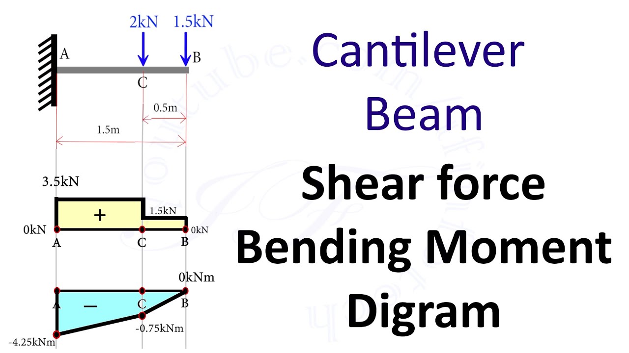
Cantilever Beam: Shear Force and Bending Moment Diagram [SFD BMD Problem 2] By Shubham Kola
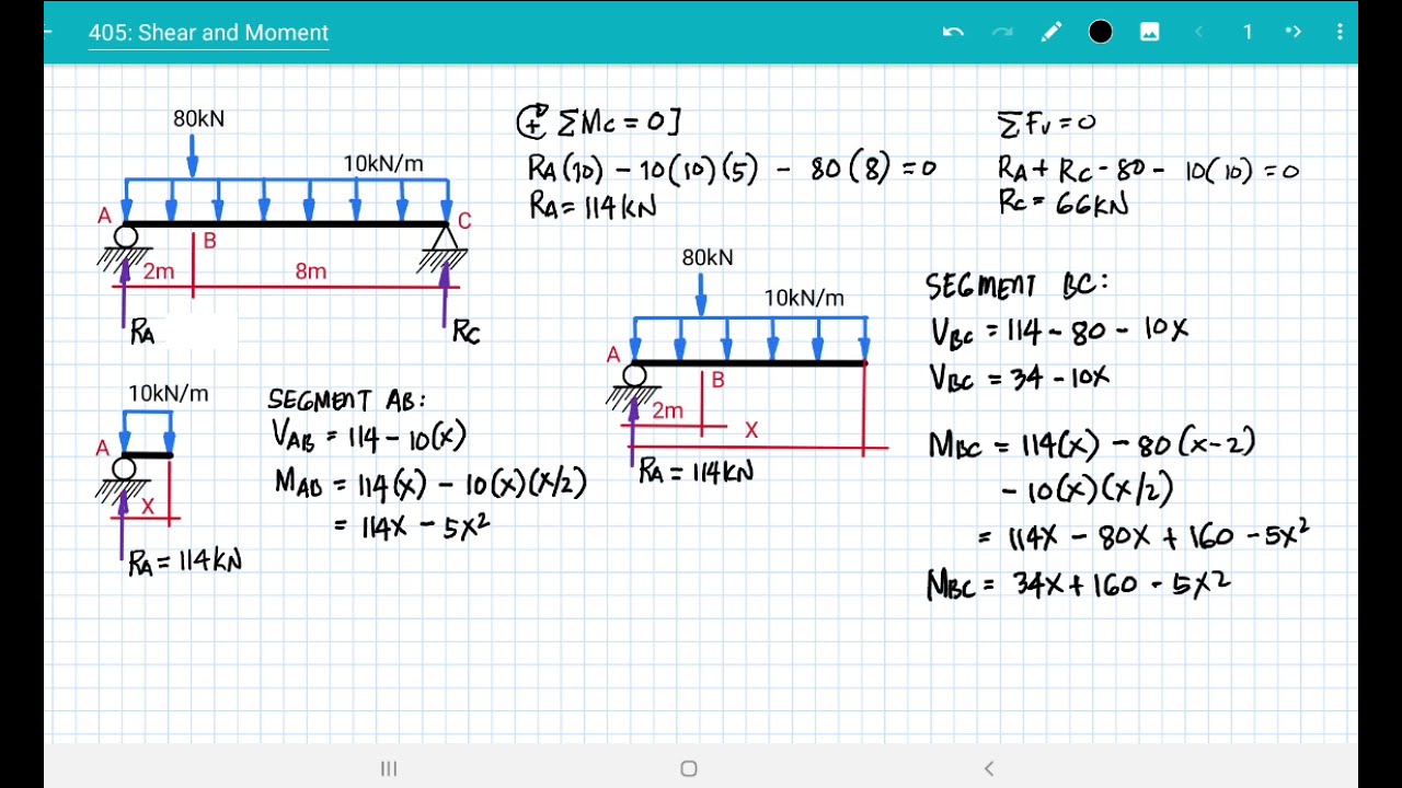
[ 405 ] SHEAR & MOMENT DIAGRAM

09-06 Tegangan geser pada balok: contoh perhitungan
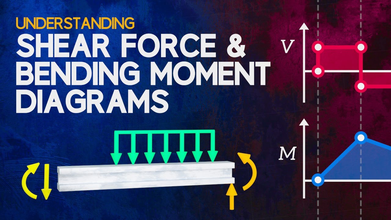
Understanding Shear Force and Bending Moment Diagrams

Statika/Mekanika Teknik #4: Gaya Dalam

Mechanics of Materials: F1-1 (Hibbeler)
5.0 / 5 (0 votes)