Mechanics of Materials: F1-1 (Hibbeler)
Summary
TLDRThis video script details a structural engineering problem involving a beam with specific support conditions and loadings. The focus is on calculating the internal normal force, shear force, and bending moment at Point C. The process involves drawing a free-body diagram, applying global equilibrium for overall system analysis, and determining reaction forces at supports A and B. The script then proceeds to find the internal forces at Point C by making an appropriate cut and analyzing the left side of the beam for normal force, shear force, and bending moment. The final results indicate a zero normal force, a shear force of 20 kN, and a bending moment of -40 kNm at Point C.
Takeaways
- 📏 The problem involves determining the normal force (N), shear force (V), and bending moment (M) at Point C of a beam.
- 🏗️ The beam is supported by a roller at A to the left of C and a pin at B to the right of C.
- ⚙️ A 60 kNm moment acts on the left end of the beam, and a 10 kN downward force acts on the right.
- 📈 The first step is to draw a free-body diagram of the entire system, including the forces and moments acting on the beam.
- 🔍 To find the reaction forces (Ay and By), moments are taken about point A, leading to the calculation of By as -10 kN.
- 📉 The normal force at C (NC) is found to be zero by considering the equilibrium in the X direction.
- 📊 The shear force at C (VC) is calculated to be 20 kN by summing forces in the Y direction.
- 📐 The bending moment at C (MC) is determined by summing moments about point C, resulting in -40 kNm.
- 🔧 The analysis uses the principles of statics to solve for the internal forces in the beam.
- 📋 The process involves making appropriate cuts in the beam to analyze the internal effects and applying the equations of equilibrium.
Q & A
What are the three internal forces to be determined in the beam at Point C?
-The three internal forces to be determined at Point C are the normal force (N), shear force (V), and bending moment (M).
What are the boundary conditions of the beam described in the script?
-The beam is supported by a roller at A to the left of C and a pin at B to the right of C.
What are the external forces and moments acting on the beam?
-There is a 60 kilonewton-meter moment acting on the left end of the beam and a downward 10 kilonewton force on the right.
How is the free-body diagram of the beam constructed?
-The free-body diagram includes the beam, the 10 kilonewton force, and the moment on the left, with vertical reaction forces at A and B, and dimensions noted.
Why are moments used to find the reaction forces instead of the sum of forces?
-Moments are used because there are two unknown reaction forces (Ay and By), and using moments allows solving for one of them without having two unknowns in a single equation.
What is the method used to find the reaction force By?
-The reaction force By is found by taking moments about point A and solving the equation for By.
What is the calculated value of By and why is it negative?
-The calculated value of By is -10 kilonewtons, which is negative because the force is acting downwards, opposite to the chosen positive direction.
How is the normal force at Point C determined?
-The normal force at Point C is determined to be zero by setting the sum of forces in the x-direction equal to zero, as there are no external forces acting in that direction.
What is the shear force VC at Point C?
-The shear force VC at Point C is 20 kilonewtons, found by setting the sum of forces in the y-direction equal to zero.
How is the bending moment MC at Point C calculated?
-The bending moment MC at Point C is calculated by summing moments about Point C, considering the applied moments and forces, resulting in -40 kilonewton-meters.
What is the significance of the negative bending moment MC?
-A negative bending moment MC indicates that the beam is bending in a clockwise direction when viewed from the left end of the beam.
Outlines

This section is available to paid users only. Please upgrade to access this part.
Upgrade NowMindmap

This section is available to paid users only. Please upgrade to access this part.
Upgrade NowKeywords

This section is available to paid users only. Please upgrade to access this part.
Upgrade NowHighlights

This section is available to paid users only. Please upgrade to access this part.
Upgrade NowTranscripts

This section is available to paid users only. Please upgrade to access this part.
Upgrade NowBrowse More Related Video

SFD and BMD - Problem 1 - Part 1 - Shear Force and Bending Moment Diagram - Strength of Materials
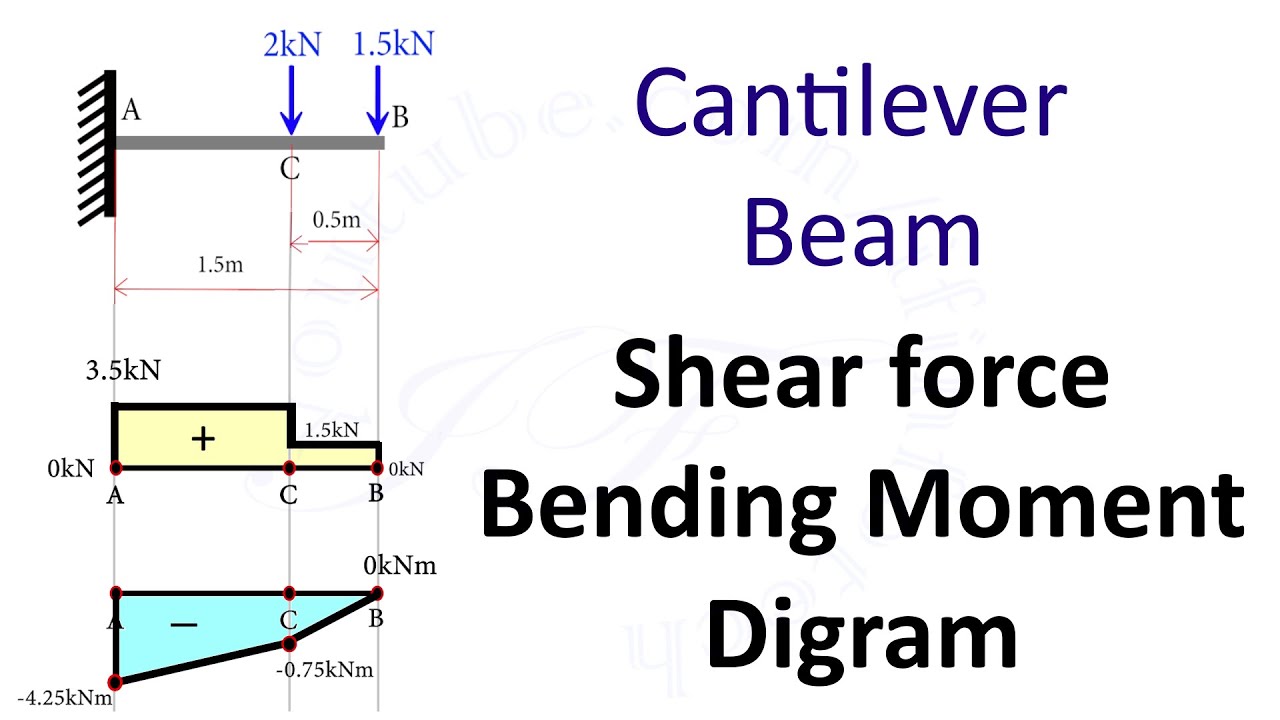
Cantilever Beam: Shear Force and Bending Moment Diagram [SFD BMD Problem 2] By Shubham Kola

Balok Penampang T SNI 2847-2019

[Struktur Baja 2]: Perhitungan Sambungan Balok-Kolom Baja
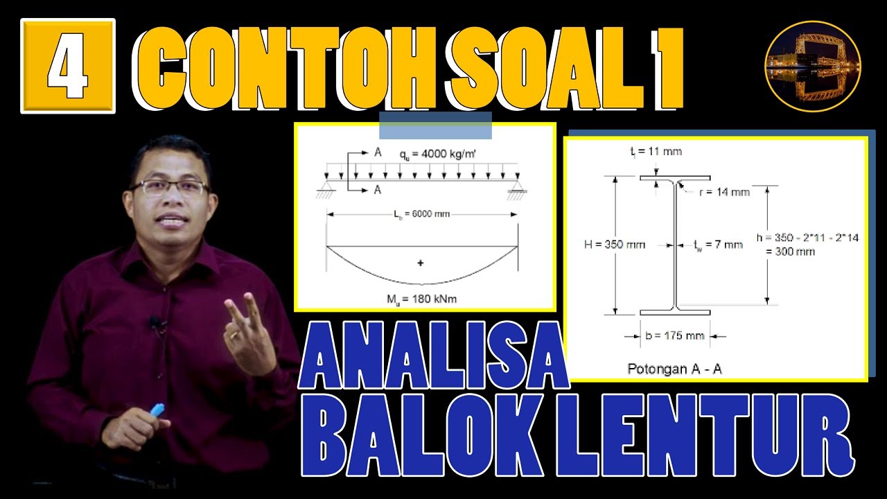
Contoh Perhitungan Analisa Balok Anak dgn Plastik Sempurna (Leleh Umum) | Struktur Baja | Lightboard
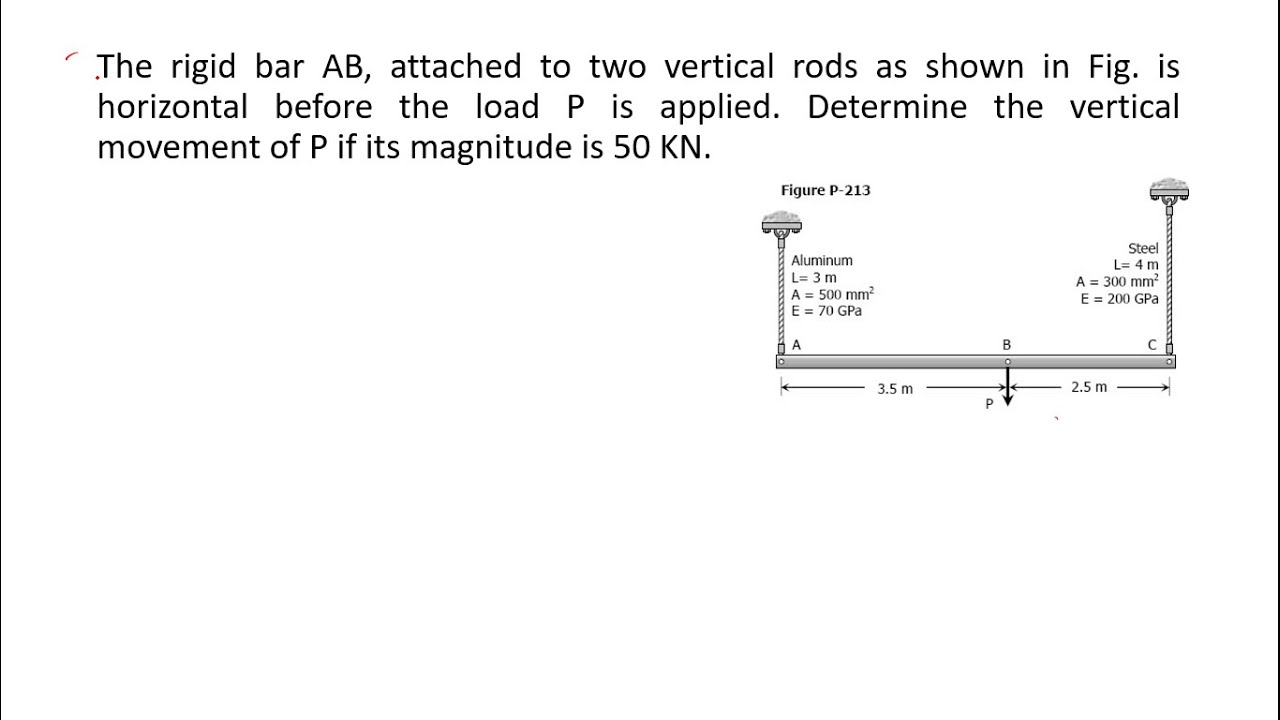
The rigid bar AB, attached to two vertical rods as shown in
5.0 / 5 (0 votes)