Tutorial Instalasi Diptrace
Summary
TLDRThis tutorial walks viewers through the installation and use of DipTrace software for creating PCB layouts. It begins with downloading and installing the software, ensuring compatibility with your computer. The video covers setting up the workspace, selecting grid sizes, and adjusting the layout for different components. It demonstrates both manual and automatic methods for connecting components, as well as how to adjust tracks and component holes. Throughout, viewers are guided on how to customize their design based on specific needs, providing a comprehensive foundation for PCB design using DipTrace.
Takeaways
- 😀 The tutorial begins with an introduction in Indonesian, focusing on teaching how to install software for creating PCB layouts.
- 😀 The software, named Dipress, can be downloaded from the internet by searching for it on Google.
- 😀 It's essential to ensure that the software version matches your computer's specifications (32-bit or 64-bit).
- 😀 The tutorial provides a step-by-step guide on how to install the Dipress software, including accepting the license agreement and choosing the installation path.
- 😀 Once installed, users are introduced to four main menus: Schematic Capture, PCB Layout, Component Editor, and Veteran Editor.
- 😀 The Schematic Capture menu allows users to create circuit schematics using symbols for components.
- 😀 The PCB Layout menu is where users design the physical layout of the PCB, placing components and routing connections.
- 😀 Users are instructed to adjust grid spacing to fit the components being used, and they learn how to set it in millimeters instead of inches for precision.
- 😀 The tutorial demonstrates how to manually connect components on the PCB layout and change the color of the PCB tracks for better visibility.
- 😀 In the final steps, the tutorial covers how to adjust hole sizes for component leads and the importance of ensuring correct spacing for the design to function properly when printed.
Q & A
What is the main purpose of this tutorial?
-The main purpose of this tutorial is to guide viewers on how to install and use Dipress PCB design software, covering tasks such as creating PCB layouts, component placement, and routing traces.
Where should viewers go to download the software?
-Viewers should search for 'Dipress' on Google, which will direct them to the official website where they can download the software.
How can viewers determine which version of the software to download?
-Viewers need to check their system specifications to see whether they are using a 32-bit or 64-bit operating system and download the appropriate version accordingly.
What are the four main features of the Dipress software introduced in the tutorial?
-The four main features of Dipress are: Schematic Capture (for circuit design), PCB Layout (for designing the PCB), Component Editor (for creating custom components), and Veterna Editor (for editing components or layouts).
How does the user switch the unit of measurement from inches to millimeters in the software?
-To switch the unit of measurement from inches to millimeters, users need to go to the settings and change the unit under the 'Grid' option to millimeters (MM).
What is the purpose of adjusting the grid size in the PCB design?
-Adjusting the grid size helps in placing components accurately on the PCB. Smaller grid sizes are used for components with smaller pins, and larger grids are used for bigger components.
What is the significance of the trace width in PCB design?
-The trace width determines the thickness of the connections between components on the PCB. It is important to adjust the trace width to ensure the PCB can handle the necessary current and to fit the design requirements.
How can users adjust the size of drill holes for components?
-Users can modify the size of drill holes by selecting the components and changing the hole size properties in the software, adjusting them to match the component's specifications.
What should users do if they make an error in the PCB layout or if the traces are incorrect?
-If an error is made, users can delete or modify the incorrect trace by selecting it and either deleting it or adjusting the routing as needed. Users can also move or shift traces to correct mistakes.
What type of components did the speaker use as an example in the tutorial?
-The speaker used an example of an 8-pin IC (Integrated Circuit) and a potentiometer to demonstrate how to place and connect components in the PCB layout.
Outlines

This section is available to paid users only. Please upgrade to access this part.
Upgrade NowMindmap

This section is available to paid users only. Please upgrade to access this part.
Upgrade NowKeywords

This section is available to paid users only. Please upgrade to access this part.
Upgrade NowHighlights

This section is available to paid users only. Please upgrade to access this part.
Upgrade NowTranscripts

This section is available to paid users only. Please upgrade to access this part.
Upgrade NowBrowse More Related Video
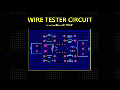
TUTORIAL DESIGN PCB WIRE TESTER USE PROTEUS 8.12 (AUTO PLACER & AUTO ROUTER)

AC to DC Power Supply Design #E04 | Vaibhav Sugandhi

Belajar MySQL untuk Pemula - Cara Download dan Install MySQL di Windows 11
Comment Installer Windows 10 Facilement ?! - Tutoriel de A à Z

Cara Install Windows 11 LENGKAP (Cara Download, Buat Bootable,Cara Install, Cara Partisi)

Tutorial Software BLOCPLAN
5.0 / 5 (0 votes)