Data Flow Diagram: Pegertian Simbol | Analisis dan Desain Sistem
Summary
TLDRIn this educational video, Vida Masrika explains the concepts and components of a Data Flow Diagram (DFD), focusing on its purpose, symbols, and the role of data flows in system design. She breaks down the four main components: external entities, processes, data flows, and data stores, emphasizing the importance of understanding how data moves within a system. Additionally, she covers different notation styles like Gane and Sarson, and DeMarco and Yourdon, illustrating how they can be used in DFDs. The video aims to prepare viewers for creating effective DFDs by highlighting key symbols and structural requirements.
Takeaways
- 😀 DFD (Data Flow Diagram) represents the flow of data in a system, focusing on how data moves rather than the sequence of actions.
- 😀 A DFD consists of four main components: External Entity, Process, Data Flow, and Data Store.
- 😀 An External Entity is something outside the system (e.g., people, organizations, other systems) that either provides input or receives output from the system.
- 😀 Processes in DFD represent activities that transform input data into output data, and they must have both input and output data flows.
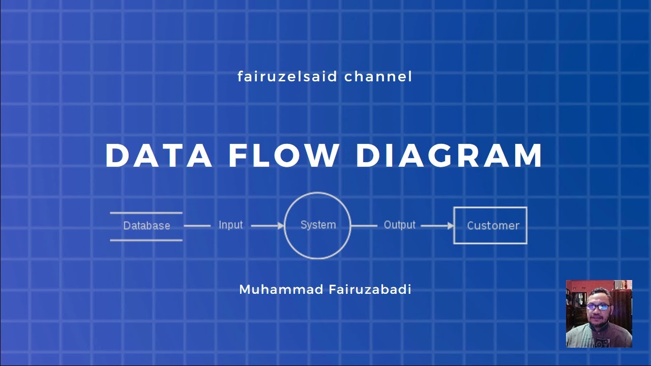
- 😀 Data Flow represents the movement of data between entities, processes, and data stores. It is depicted by arrows and should be clearly named.
- 😀 Data Stores represent data storage locations, such as files or databases, and must have both input and output data flows.
- 😀 Each component of a DFD is symbolized by specific shapes. External Entities are represented by rectangles, Processes by circles, Data Flows by arrows, and Data Stores by horizontal rectangles.
- 😀 The identification numbers of processes in a DFD do not represent the execution order but serve as unique identifiers.
- 😀 Process names in DFDs should be verbs that clearly describe the activity being performed (e.g., 'Place Order').
- 😀 A proper DFD must ensure that each process and data store adheres to the rule of having at least one input and one output data flow.
- 😀 The next video will focus on how to draw a DFD, covering key considerations in creating accurate and clear diagrams.
Q & A
What is the main focus of the video?
-The main focus of the video is explaining the concept of Data Flow Diagrams (DFD), their functions, and the symbols used in DFDs to represent data movement in systems.
Why is it recommended to watch previous videos before this one?
-It is recommended to watch previous videos because they cover system requirements gathering, which is closely related to the material discussed in the Data Flow Diagram video.
What are the key components of a Data Flow Diagram (DFD)?
-The key components of a DFD are External Entities, Processes, Data Flows, and Data Stores.
What is the role of an 'External Entity' in a Data Flow Diagram?
-An External Entity is an outside system, person, or organization that interacts with the system being modeled. It can either provide input to the system or receive output from the system, or both.
What are the two types of symbols used for External Entities in DFDs?
-The two types of symbols used for External Entities in DFDs are Gane and Sarson, and DeMarco and Yourdon. Both use a box, but they have slightly different styles.
What defines the naming convention for External Entities in a DFD?
-External Entities are named using nouns that clearly describe the entity's role, such as 'Customer', 'Supplier', or 'Warehouse'. The name should reflect the entity’s function in the system.
What is the minimum requirement for a Process symbol in a DFD?
-A Process must have at least one input data flow and one output data flow. This ensures that data is being processed and returned to the system.
What type of word should be used in naming a Process in a DFD?
-Processes should be named using verbs, which describe the action being performed, such as 'Process Order' or 'Verify Data'. The name should clearly describe what the process does.
What is a Data Flow in a Data Flow Diagram?
-A Data Flow represents the movement of data within the system. It is depicted by an arrow pointing from one component to another, showing the input or output of data in the system.
What must be true about Data Stores in a Data Flow Diagram?
-A Data Store represents a repository of data, such as a database or file. Each Data Store must have at least one input data flow and one output data flow. The Data Store’s name should reflect the data it contains, such as 'Customer Data' or 'Order Records'.
Outlines

This section is available to paid users only. Please upgrade to access this part.
Upgrade NowMindmap

This section is available to paid users only. Please upgrade to access this part.
Upgrade NowKeywords

This section is available to paid users only. Please upgrade to access this part.
Upgrade NowHighlights

This section is available to paid users only. Please upgrade to access this part.
Upgrade NowTranscripts

This section is available to paid users only. Please upgrade to access this part.
Upgrade NowBrowse More Related Video

Data Flow Diagram Level 0 | Analisis dan Desain Sistem

Belajar Sistem Informasi | 5. Mengenal Data Flow Diagram (DFD)
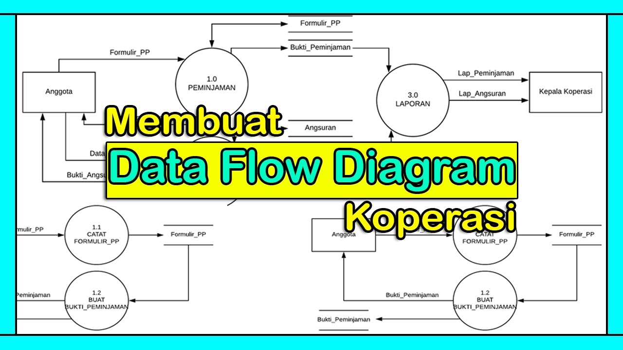
Tutorial Membuat DFD (Data Flow Diagram) | Studi Kasus Koperasi
Data Flow Diagram (DFD): Definisi, Sejarah, Notasi, Tahap dan Tipsnya.

What is DFD? How to design DFD, Symbols, examples full explanation

#Matakuliah RPL | Pemodelan Proses (DFD)
5.0 / 5 (0 votes)