Analisis Siklus Refrigerasi Kompresi Uap Ideal
Summary
TLDRIn this video, the speaker provides a detailed explanation of the vapor compression refrigeration cycle, focusing on analyzing the cycle's components and calculating the cooling capacity of an air conditioning system. Using the refrigerant R134a, the speaker demonstrates how to determine key properties such as enthalpy and entropy at different states of the refrigerant. Through an example problem involving a compressor with 0.5 HP capacity, the video guides viewers step-by-step in applying thermodynamic principles to calculate the cooling capacity, ultimately arriving at a result of 1.86 kW. This practical demonstration enhances the understanding of refrigeration cycles in real-world applications.
Takeaways
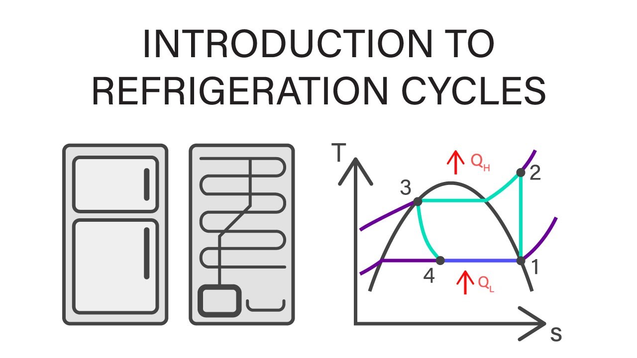
- 😀 The script focuses on explaining the vapor compression refrigeration cycle (VCRS) and its key components like the compressor, condenser, expansion valve, and evaporator.
- 😀 It starts with a review of the ideal refrigeration cycle and then transitions into analyzing a practical example using real-world data from an air conditioning (AC) system.
- 😀 The cooling capacity of the AC is determined by calculating the heat absorbed in the evaporator, using the enthalpies at various points in the refrigeration cycle.
- 😀 The refrigerant used in the system is R134a, and key properties like pressure and enthalpy at different points are referenced from refrigerant tables.
- 😀 The problem provides a compressor power of 0.5 horsepower, which is converted to 3728 watts for use in calculations.
- 😀 The cycle is considered ideal, meaning processes are assumed to be isentropic (no entropy change) in the compressor, and the evaporator and condenser operate at saturation conditions.
- 😀 Pressures in the system are given as 1.4 MPa (high pressure) and 400 kPa (low pressure), and the system is designed to maintain these pressure levels during operation.
- 😀 The process involves calculating the mass flow rate of the refrigerant (m_dot), which is essential for determining the cooling capacity and understanding the system's energy balance.
- 😀 The specific entropies at different points in the cycle (S1, S2, etc.) are key to determining the efficiency and work done by the compressor.
- 😀 The final cooling capacity is calculated by evaluating the heat removed by the evaporator, which is found to be approximately 1.86 kW after applying the necessary thermodynamic equations.
Q & A
What is the main topic of the video?
-The video discusses the refrigeration cycle of a vapor compression system (SR), with a focus on calculating the cooling capacity of an air conditioning system using R134a refrigerant.
What refrigerant is used in the system described in the video?
-The refrigerant used in the system is R134a.
What is the compressor capacity in horsepower and watts?
-The compressor capacity is 0.5 horsepower, which is approximately 3728 watts.
What are the high and low pressure values of the system?
-The high pressure is 1.4 MPa and the low pressure is 400 kPa.
What is the purpose of the video?
-The video aims to explain and analyze the refrigeration cycle, focusing on how to calculate the cooling capacity and understand the thermodynamic processes involved in the cycle.
What is the process involved in the refrigeration cycle described in the video?
-The refrigeration cycle consists of four main stages: compression (from low pressure to high pressure), condensation (gas to liquid), expansion (pressure reduction), and evaporation (liquid to gas at low pressure).
How is the enthalpy at each state determined in the cycle?
-The enthalpy at each state is determined using refrigerant tables (R134a in this case) and properties like pressure and entropy. For example, at state 1, the refrigerant is a saturated gas at low pressure, and its enthalpy is calculated using the R134a tables.
How is the mass flow rate (ṁ) calculated?
-The mass flow rate is calculated using the work input to the compressor. Given the compressor capacity and enthalpies at states 1 and 2, the mass flow rate is derived using the formula ṁ = Wc / (h2 - h1), where Wc is the compressor work.
What is the cooling capacity of the system as calculated in the video?
-The cooling capacity of the system is calculated to be approximately 1.86 kW.
What assumption is made regarding the refrigeration cycle in the analysis?
-The analysis assumes an ideal refrigeration cycle, meaning there are no losses or inefficiencies in the system.
Outlines

This section is available to paid users only. Please upgrade to access this part.
Upgrade NowMindmap

This section is available to paid users only. Please upgrade to access this part.
Upgrade NowKeywords

This section is available to paid users only. Please upgrade to access this part.
Upgrade NowHighlights

This section is available to paid users only. Please upgrade to access this part.
Upgrade NowTranscripts

This section is available to paid users only. Please upgrade to access this part.
Upgrade NowBrowse More Related Video


5.0 / 5 (0 votes)