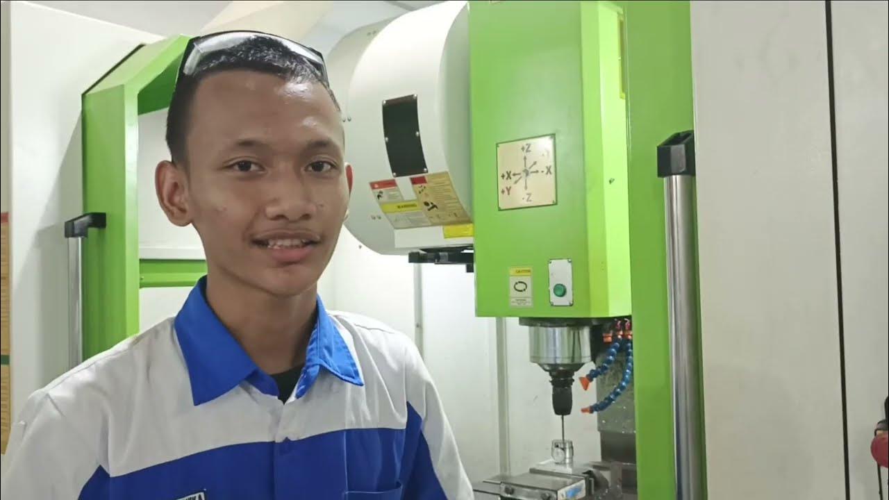
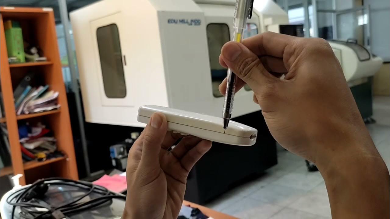
Pengaturan titik nol pada sumbu X,Y dan Z pada Frank Cam Mill - Renan
Summary
TLDRThis video provides a step-by-step guide for setting up and calibrating the X, Y, and Z axes of a machine, likely a CNC or similar automated system. It covers crucial steps such as tool positioning, accessing and inputting programs, setting offsets, and ensuring correct alignment using different tools and machine settings. The script emphasizes attention to detail in the setup process, ensuring tools and components are properly calibrated and secured. Viewers can expect a thorough walkthrough on configuring machine parameters for accurate and efficient operation.
Takeaways
- 😀 Ensure that protection and competition settings are saved correctly in the designated folder before starting.
- 😀 The first step in setting X, Y, and Z is knowing the positions of the tool or parts, such as the cutting tool or organelle.
- 😀 You can use templates or diamond collars to set the X and Y axes in the machine simulation.
- 😀 Always check the tool's position, such as tool number 99, and recall its specific location using the MBC selector and program.
- 😀 When adjusting the X-axis, use single mode to move it step by step and ensure precise alignment.
- 😀 After setting the X-axis, verify the position again to ensure it's correctly aligned at the origin point (X0, Y0, Z0).
- 😀 For setting the Z-axis, confirm the tool diameter and its corresponding program number to ensure proper alignment.
- 😀 Use offset values, such as 0.4, to adjust the tool’s position and avoid errors in the measurement.
- 😀 Always verify the settings, especially when transitioning between different machine settings (e.g., X, Y, Z), to ensure they are accurate.
- 😀 If necessary, input the tool diameter or offsets correctly to avoid issues, and test the position of the tool multiple times to confirm accuracy.
Q & A
What is the first step to set up the CNC machine according to the script?
-The first step is to ensure that the machine's configuration is saved and protected in the designated folder.
How should the position of the cutting tool be checked?
-The position of the cutting tool can be checked by referring to the image or selector on the machine, such as checking the tool's number (e.g., tool number 99).
What is the purpose of entering the code 'T99' in the machine program?
-'T99' is used to call a specific tool on the machine, allowing for accurate tool selection during setup.
How can you confirm that the tool has been correctly replaced?
-After replacing the tool, the machine should be tested, and the setup can be checked by using functions like 'G0' and verifying the movement of the tool.
What does the term 'offset' refer to in the setup process?
-In this context, 'offset' refers to the adjustment made to the position of the tool or workpiece to ensure correct machining. The offset value must be set precisely (e.g., 0.4 or 50).
Why is it important to verify the tool’s position in multiple steps?
-Verifying the tool's position in multiple steps ensures that there are no misalignments, preventing errors during machining and improving the precision of the workpiece.
How are the X, Y, and Z axes adjusted in the setup?
-The X, Y, and Z axes are adjusted by moving the tool or workpiece to specific positions using the machine's control panel, and further refined by checking offsets and adjusting the settings accordingly.
What should be done if the tool position is still not accurate after adjustments?
-If the position is not accurate, further adjustments to the offsets or tool selection should be made. The process of verifying and correcting the position should continue until accuracy is achieved.
How does the script describe the process of calibrating the Z-axis?
-The Z-axis calibration involves checking the tool's position, adjusting it, and ensuring the correct tool (e.g., tool number 1 with a diameter of 12) is selected. This is followed by checking the machine’s settings and ensuring the correct offsets are applied.
What safety measures are mentioned in the script during the setup process?
-The script mentions the importance of using protective gear and being cautious when handling tools or performing adjustments to avoid accidents.
Outlines

This section is available to paid users only. Please upgrade to access this part.
Upgrade NowMindmap

This section is available to paid users only. Please upgrade to access this part.
Upgrade NowKeywords

This section is available to paid users only. Please upgrade to access this part.
Upgrade NowHighlights

This section is available to paid users only. Please upgrade to access this part.
Upgrade NowTranscripts

This section is available to paid users only. Please upgrade to access this part.
Upgrade Now5.0 / 5 (0 votes)


