Aula 05 - Aula de Comandos 03 - AutoCAD
Summary
TLDRIn this AutoCAD tutorial, the instructor demonstrates how to use the **Chamfer** and **Fillet** commands to modify corners between two lines. The Chamfer command is explained with an emphasis on adjusting bevel distances, while the Fillet command is used to create rounded corners by specifying a radius. The video provides clear, step-by-step instructions on how to adjust these parameters, including using zero distances for sharp corners and non-zero values for beveled or rounded edges. The tutorial is beginner-friendly, making it ideal for learning essential AutoCAD techniques for corner modifications.
Takeaways
- 😀 Chamfer command is used to create angled edges or chamfers between two lines.
- 😀 Fillet command is used to create rounded or curved corners between two lines.
- 😀 The Chamfer command has options to modify distances along the X and Y axes from the intersection point.
- 😀 In Chamfer, the first and second distances can be adjusted using the 'D' key to set custom measurements.
- 😀 A Chamfer with zero distance creates a simple union of two lines without any displacement.
- 😀 The Fillet command creates smooth, rounded corners by defining a radius between two intersecting lines.
- 😀 The 'F' key is the shortcut to enter the Fillet command quickly, without needing to type the full command.
- 😀 In Fillet, you can change the radius of the arc by pressing 'R' and entering a desired radius value.
- 😀 A Fillet with a zero radius results in the two lines simply joining at the intersection point.
- 😀 Using the Fillet command with a radius greater than zero will create a smooth curve, cutting off excess parts of the lines.
- 😀 The Trim mode in both Chamfer and Fillet helps cut off excess line segments when they extend beyond the intended point.
Q & A
What is the purpose of the Chamfer command in AutoCAD?
-The Chamfer command in AutoCAD is used to create beveled edges, also known as chamfers, between two lines or objects. It allows users to join lines with an angled edge instead of a sharp corner.
How do you activate the Chamfer command in AutoCAD?
-To activate the Chamfer command, type 'C' on the keyboard or use the 'Chamfer' option from the toolbar. The command can also be accessed by typing 'CHA' in the command line.
What is the function of the 'Distance' parameter in the Chamfer command?
-The 'Distance' parameter in the Chamfer command defines how far the lines will be offset from the intersection point. It allows you to control the size of the chamfer by setting two distances for each segment of the beveled edge.
What happens when you set the distances to zero in the Chamfer command?
-Setting both distances to zero in the Chamfer command will cause the two lines to meet at the intersection point without any beveled edge. This results in the lines being joined directly without any chamfer.
How is the Fillet command different from the Chamfer command in AutoCAD?
-The Fillet command creates a rounded corner (arc) between two lines, while the Chamfer command creates a beveled or straight-edged corner. Fillet allows for radius control, while Chamfer adjusts the angles.
How can you change the radius in the Fillet command?
-To change the radius in the Fillet command, type 'R' (for radius) after entering the command and then specify the desired radius. This creates a rounded corner between the two lines with the specified radius.
What does the 'Trim' mode in the Fillet command do?
-The 'Trim' mode in the Fillet command automatically removes any parts of the lines that extend beyond the intersection point, ensuring that the lines are joined smoothly at the corner without excess line segments.
What does the term 'Tri-mode' refer to in the Chamfer and Fillet commands?
-The 'Tri-mode' refers to the feature in both Chamfer and Fillet commands where the software adjusts or trims parts of the lines based on the selected distances or radius. It automatically removes extra parts of lines that exceed the defined parameters.
What does the Fillet command do if the radius is set to zero?
-If the radius is set to zero in the Fillet command, it will effectively create a sharp, 90-degree corner between the two lines, just like the Chamfer command with zero distance.
Why is it important to understand the difference between Chamfer and Fillet in AutoCAD?
-Understanding the difference between Chamfer and Fillet is crucial for precise design. Chamfer creates angled edges, while Fillet creates smooth, rounded corners. Knowing when to use each can improve your design workflow and the final output of your drawings.
Outlines

This section is available to paid users only. Please upgrade to access this part.
Upgrade NowMindmap

This section is available to paid users only. Please upgrade to access this part.
Upgrade NowKeywords

This section is available to paid users only. Please upgrade to access this part.
Upgrade NowHighlights

This section is available to paid users only. Please upgrade to access this part.
Upgrade NowTranscripts

This section is available to paid users only. Please upgrade to access this part.
Upgrade NowBrowse More Related Video
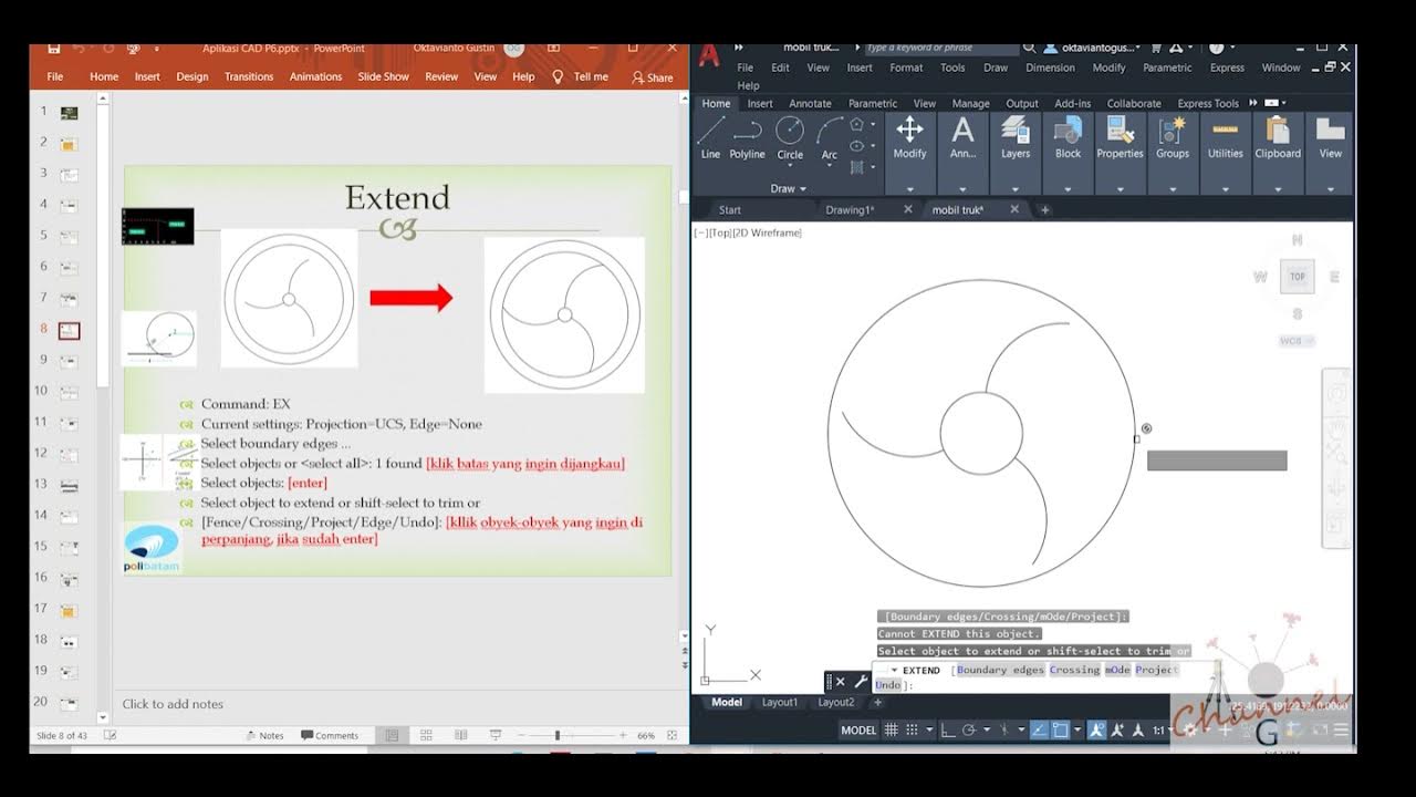
AutoCAD - Merubah Obyek (Offset, extend, fillet, linetype, devide, Point Style)
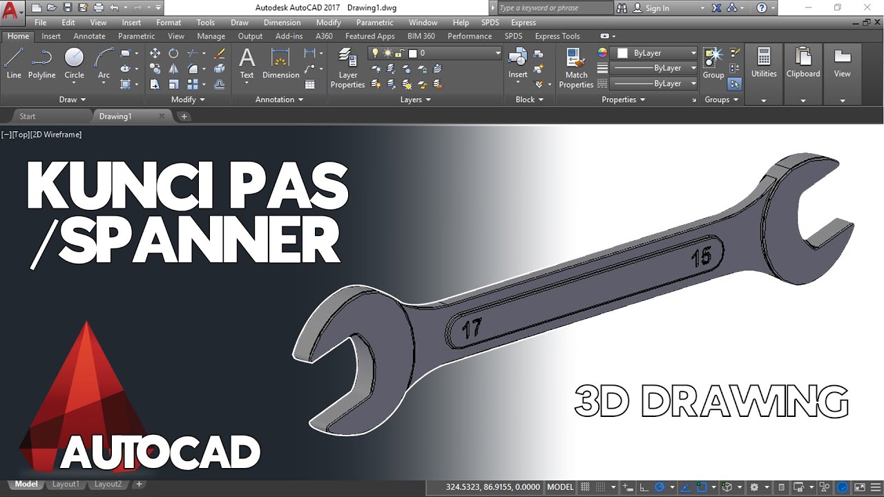
Cara Menggambar Kunci Pas / Spanner di AutoCAD
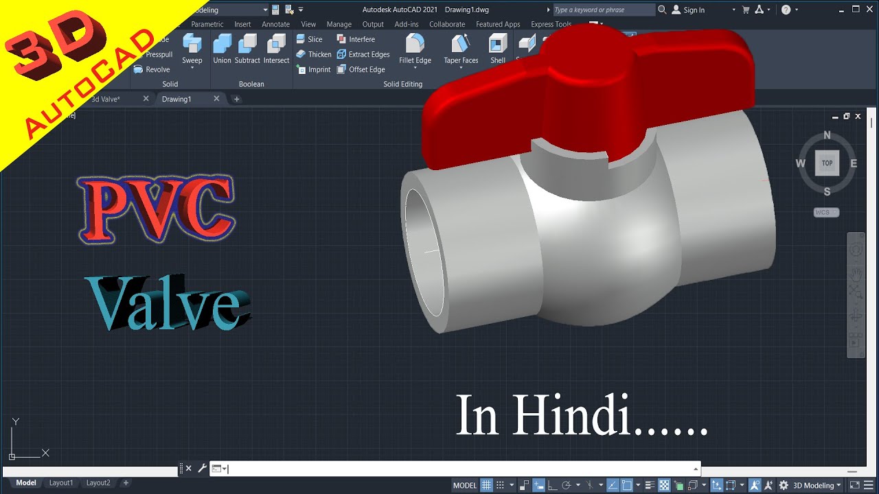
How to draw PVC Valve in AutoCAD 3D. #autocad_hindi_tutorial #autocaddrawing
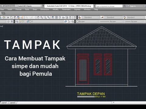
Cara mudah Membuat Tampak - Tutorial autoCAD
Cara Membuat Garis Tepi dan Etiket Gambar Teknik Kertas A4 di Autodesk AutoCad
AutoCAD Tutorial for Beginners - 4
5.0 / 5 (0 votes)