Listrik Dinamis-Rangkaian Listrik (Hukum Ohm) (Part 3)
Summary
TLDRThis video provides an in-depth explanation of electric circuits, focusing on the concepts of resistors, series, parallel, and combined circuits. It covers how resistors control the flow of electrical current and how to calculate equivalent resistances in different circuit configurations. The video also explains Ohm’s Law, detailing the relationship between current, voltage, and resistance, with practical examples of solving circuit problems. Viewers will learn how to calculate total resistance for series and parallel circuits, as well as apply Ohm’s Law to find voltage in real-world scenarios, helping them understand electrical concepts more effectively.
Takeaways
- 😀 Electric current flows from the positive pole (higher potential) to the negative pole (lower potential).
- 😀 A resistor (or 'hambatan') controls the flow of electric current by offering resistance, preventing short circuits.
- 😀 Resistors are denoted by the letter 'R' and measured in Ohms (Ω), with the symbol resembling a horseshoe.
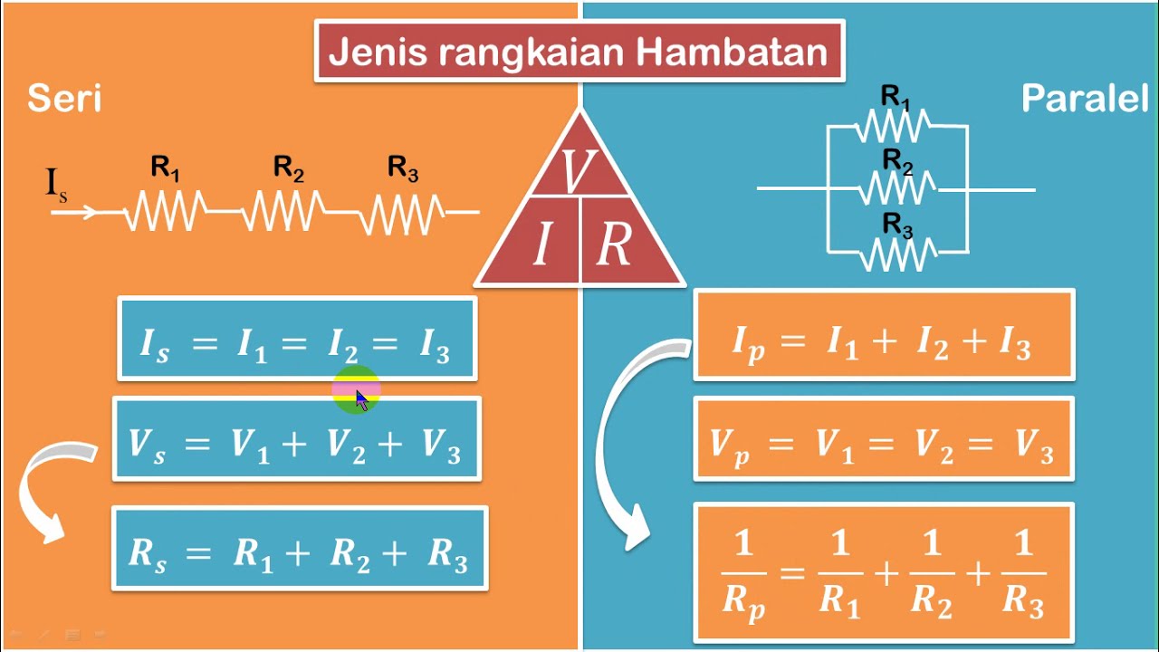
- 😀 Series circuits have no branches and are represented by a straight or bent line without branching points.
- 😀 To calculate the equivalent resistance in a series circuit, simply sum the individual resistances: R_series = R1 + R2 + R3, etc.
- 😀 Parallel circuits involve branching points where the resistors are placed side-by-side, resulting in a lower overall resistance.
- 😀 The formula to calculate equivalent resistance in a parallel circuit is: 1/R_parallel = 1/R1 + 1/R2 + 1/R3, etc.
- 😀 In parallel circuits, it’s important to equalize fractions by finding a common denominator before solving.
- 😀 A combination of series and parallel resistors requires first solving the parallel resistors and then considering the series configuration.
- 😀 Ohm’s Law states that the current through a conductor is directly proportional to the voltage across it and inversely proportional to the resistance, expressed as I = V/R.
- 😀 In combined series-parallel circuits, first calculate the series resistance, then apply the parallel formula for the resulting resistances.
Q & A
What is the function of a resistor in an electrical circuit?
-A resistor functions to limit or control the flow of electric current in a circuit. It resists the flow of current, preventing issues like short circuits that could occur without it.
How is the resistance of a series circuit calculated?
-The total resistance in a series circuit is calculated by simply adding the individual resistances. The formula is: R_series = R1 + R2 + R3 + ... (depending on the number of resistors).
What are the characteristics of a parallel circuit?
-In a parallel circuit, resistors are connected in such a way that there are branching paths for the current. This type of connection lowers the overall resistance of the circuit.
How is the equivalent resistance of a parallel circuit calculated?
-The equivalent resistance for a parallel circuit is calculated using the formula: 1/R_parallel = 1/R1 + 1/R2 + 1/R3 + ... (depending on the number of resistors). After calculating this sum, you invert the result to find R_parallel.
What is the difference between a series circuit and a parallel circuit?
-In a series circuit, resistors are connected in a single line, causing the current to pass through each resistor one after the other. In contrast, a parallel circuit has branching paths, allowing current to split and flow through multiple resistors simultaneously.
How is the equivalent resistance for a combined series and parallel circuit calculated?
-For a circuit with both series and parallel resistors, you first calculate the equivalent resistance of the parallel section, then add it to the resistance of the series section. The order of calculations depends on the arrangement in the circuit.
What is Ohm's Law and how is it used in circuit analysis?
-Ohm's Law states that the electric current (I) passing through a conductor is directly proportional to the voltage (V) and inversely proportional to the resistance (R). It is expressed as V = I * R. This law helps to calculate voltage, current, or resistance in a circuit.
How do you apply Ohm’s Law to find the voltage across a resistor in a circuit?
-To find the voltage across a resistor, you multiply the current (I) flowing through the circuit by the resistance (R) of the resistor. The formula is V = I * R.
What happens to the total resistance in a parallel circuit as more resistors are added?
-In a parallel circuit, the total resistance decreases as more resistors are added. This occurs because adding more branches for the current to flow through reduces the overall opposition to the current.
In a series circuit, how does adding more resistors affect the total current?
-In a series circuit, adding more resistors increases the total resistance, which in turn reduces the overall current in the circuit, according to Ohm's Law.
Outlines

This section is available to paid users only. Please upgrade to access this part.
Upgrade NowMindmap

This section is available to paid users only. Please upgrade to access this part.
Upgrade NowKeywords

This section is available to paid users only. Please upgrade to access this part.
Upgrade NowHighlights

This section is available to paid users only. Please upgrade to access this part.
Upgrade NowTranscripts

This section is available to paid users only. Please upgrade to access this part.
Upgrade NowBrowse More Related Video

Resistive circuits in series

ASSOCIAÇÃO DE RESISTORES: em série e em paralelo | Cortes dos Aulões do Enem | Física | Antônio

More Essentials about Circuits

Series & Parallel Circuits EXPLAINED with Kirchhoff's Circuit Laws // HSC Physics

[NEW VERSION!] RANGKAIAN PARALEL DAN SERI PARALEL | Rangkaian Listik Arus Searah - Fisika Kelas 12
IPA Kelas 9 : Listrik Dinamis 3 (Rangkaian Hambatan Seri dan Paralel)
5.0 / 5 (0 votes)