Series & Parallel Circuits EXPLAINED with Kirchhoff's Circuit Laws // HSC Physics
Summary
TLDRThis video provides a comprehensive introduction to electric circuits, covering both series and parallel configurations. Key concepts like current, voltage, and resistance are explained, along with Kirchhoff's Voltage and Current Laws. The video also highlights the importance of understanding circuit components, such as batteries, resistors, switches, lamps, voltmeters, and ammeters. The differences between series and parallel circuits are explored, with examples demonstrating how current and voltage behave in each. By the end, viewers will grasp essential circuit analysis techniques and how to measure electrical properties accurately.
Takeaways
- 😀 Current is the flow of charge over time, defined by the equation I = Q / T, where Q is charge and T is time.
- 😀 Voltage is the work done per unit charge, and it's calculated as V = W / Q, where W is work and Q is charge.
- 😀 Electrical resistance is the opposition to current flow, and it can be calculated using Ohm's law: V = IR.
- 😀 A battery provides voltage (potential difference), with the longer line being the positive terminal and the shorter line being negative.
- 😀 Resistors in a circuit impede the flow of current, and a variable resistor can be adjusted to change the circuit's resistance.
- 😀 A switch controls whether the circuit is open (no current) or closed (current can flow).
- 😀 In a series circuit, current is the same through all components, and total resistance is the sum of individual resistances.
- 😀 Ohm's law applies in both series and parallel circuits, where V = IR. In series circuits, voltage drops across resistors based on their resistance.
- 😀 Kirchhoff's Voltage Law states that the sum of all voltages around a closed loop equals zero, ensuring energy conservation.
- 😀 In parallel circuits, current splits based on resistance, but voltage remains constant across all components.
- 😀 An ammeter measures current and should be connected in series with the component, while a voltmeter measures potential difference and is connected in parallel.
Q & A
What is the definition of current in an electric circuit?
-Current is defined as the flow of electric charge. It is measured by the amount of charge (q) passing through a point in the circuit per unit time (T), expressed as I = q / T.
How is voltage defined and calculated?
-Voltage is the work done on a charge divided by the amount of charge (Q). It represents the energy transferred to the charge in a circuit and is calculated as Voltage = Work / Q.
What is electrical resistance and how does it relate to current flow?
-Electrical resistance is the opposition to the flow of current through a material. It impedes the movement of electric charge, and Ohm's law states that current is inversely proportional to resistance at a given voltage.
What does Ohm's law state and how is it applied?
-Ohm's law states that the current flowing through a conductor is directly proportional to the voltage applied across it and inversely proportional to its resistance. Mathematically, it’s represented as V = I * R.
What are the common ways to represent resistors in circuit diagrams?
-Resistors in circuit diagrams can be represented either by a zigzag line or a rectangle. Both are equivalent, and it's simply a matter of personal or institutional preference.
What is Kirchhoff's Voltage Law (KVL)?
-Kirchhoff's Voltage Law states that the sum of all voltage drops in a closed loop must equal zero. This reflects the conservation of energy, where the total energy supplied by the battery is used up by the resistors.
How do components connected in series behave in terms of current and voltage?
-In a series circuit, the current is the same through all components. The total resistance is the sum of the individual resistances, and the total voltage is divided among the components according to their resistance.
How do you calculate the total resistance in a series circuit?
-The total resistance in a series circuit is the sum of the resistances of all the components. For example, if you have resistors R1, R2, and R3, the total resistance would be R_total = R1 + R2 + R3.
What is the behavior of current and voltage in a parallel circuit?
-In a parallel circuit, the current splits across multiple paths. The total current is the sum of the currents through each path, while the voltage across all components in parallel remains the same.
How do you calculate the total resistance in a parallel circuit?
-The total resistance in a parallel circuit is found by taking the reciprocal of the sum of the reciprocals of each individual resistance. The formula is 1 / R_parallel = 1 / R1 + 1 / R2 + 1 / R3.
What is the difference between an ammeter and a voltmeter, and how are they used in circuits?
-An ammeter measures the current flowing through a circuit and should be connected in series. It should have low resistance to avoid affecting the current. A voltmeter measures the potential difference (voltage) between two points in a circuit and should be connected in parallel. It ideally has high resistance to avoid affecting the current.
What is the significance of Kirchhoff's Current Law (KCL) in parallel circuits?
-Kirchhoff's Current Law states that the total current entering a junction is equal to the sum of the currents leaving the junction. In parallel circuits, this ensures the total current is conserved as it splits among multiple paths.
Outlines

This section is available to paid users only. Please upgrade to access this part.
Upgrade NowMindmap

This section is available to paid users only. Please upgrade to access this part.
Upgrade NowKeywords

This section is available to paid users only. Please upgrade to access this part.
Upgrade NowHighlights

This section is available to paid users only. Please upgrade to access this part.
Upgrade NowTranscripts

This section is available to paid users only. Please upgrade to access this part.
Upgrade NowBrowse More Related Video

ФИЗИКА ЗА 5 МИНУТ - ЭЛЕКТРОДИНАМИКА

More Essentials about Circuits
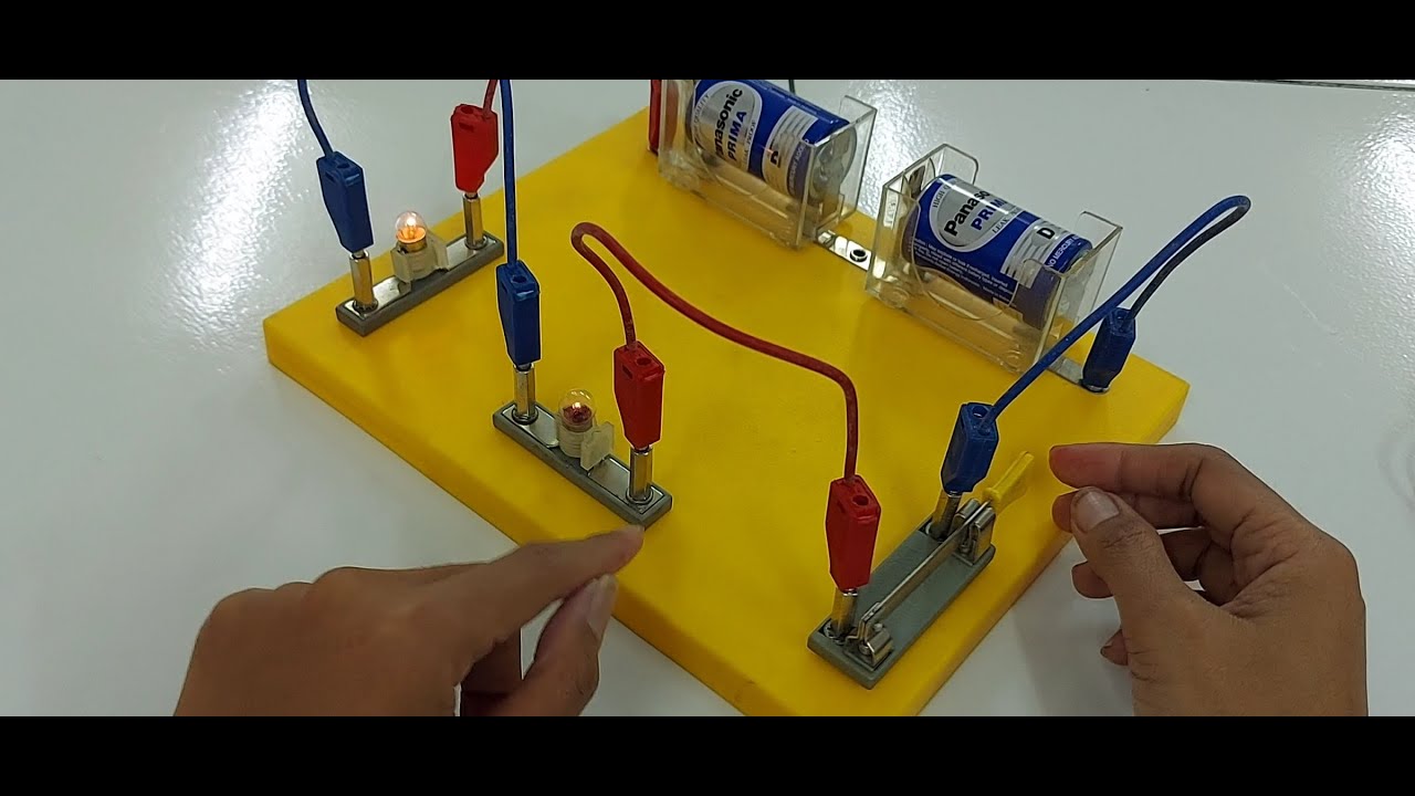
Video Pembelajaran IPA Rangkaian Listrik Seri dan Paralel menggunakan KIT

Listrik Dinamis-Rangkaian Listrik (Hukum Ohm) (Part 3)

GCSE Physics - Electricity 3 - Parallel and Series Circuits and Diagrams
Hambatan Pengganti Rangkaian Seri, Paralel Dan Campuran
5.0 / 5 (0 votes)