First angles vs Third angle method | Orthographic projections animation
Summary
TLDRThis video explains the fundamentals of orthographic projection, a crucial technique in engineering drawing. It covers the two primary methods: First Angle and Third Angle projection, detailing how 3D objects are represented on 2D planes with front, top, and side views. The script explores the quadrant system, projection rules, and the reasoning behind why the second and fourth angle projections are not used. The video is designed to help viewers understand how to create accurate and standardized technical drawings for parts and components using these projection methods.
Takeaways
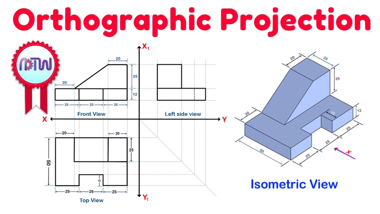
- 😀 Orthographic projection is a method used to represent 3D objects on 2D planes, showing multiple views like front, top, and side views.
- 😀 The projection system follows a quadrant system, with two planes (horizontal and vertical) dividing the space into four quadrants.
- 😀 The first quadrant is where the object is placed for the first angle projection, with the viewer between the object and the projection plane.
- 😀 In the first angle method, the front view is projected onto the vertical plane, the top view onto the horizontal plane, and side views onto profile planes.
- 😀 The third angle method places the object in the third quadrant, with the projection plane between the viewer and the object.
- 😀 In the third angle method, the front view is projected onto the vertical plane, the top view onto the horizontal plane, and side views onto the profile planes.
- 😀 The unfolded projection in the first angle method places the front view at the top, the top view below, and side views to the left and right of the front view.
- 😀 In the third angle method, the front view is at the bottom, the top view is above, and side views are on the left and right of the front view.
- 😀 Symbols are used to represent the first and third angle methods in technical drawings to avoid confusion.
- 😀 The second and fourth angle methods are not used because of projection overlap problems that make it impossible to clearly display 3D objects.
Q & A
What is orthographic projection in engineering drawing?
-Orthographic projection is a method used in engineering drawing to represent 3D objects in 2D. It involves showing multiple views of an object such as front, top, and side views on planes like the x and y planes, following specific projection rules.
What are the two main methods used for orthographic projection?
-The two main methods used for orthographic projection are the first angle method and the third angle method.
What is the quadrant system in orthographic projection?
-The quadrant system divides a 2D plane into four regions (quadrants) using the x and y axes. The quadrants are numbered in an anticlockwise direction starting from the upper right corner.
How does the first angle method work in orthographic projection?
-In the first angle method, the object is placed in the first quadrant, between the viewer and the plane of projection. The front view is projected onto the vertical plane, the top view on the horizontal plane, and the side views are projected onto profile planes placed on either side of the object.
How are the views arranged on the drawing sheet in the first angle method?
-In the first angle method, the front view is placed at the center, with the top view below it, the left-hand side view to the right, and the right-hand side view to the left.
What is the third angle method in orthographic projection?
-In the third angle method, the object is placed in the third quadrant, with the projection planes between the object and the viewer. The front view is projected onto the vertical plane, the top view onto the horizontal plane, and the side views onto profile planes.
How are the views arranged in the third angle method?
-In the third angle method, the front view is placed at the center, the top view is placed above it, the left-hand side view is to the left, and the right-hand side view is to the right.
Why are the second and fourth angle methods not used in orthographic projection?
-The second and fourth angle methods are not used because they lead to overlapping projections when the planes are rotated, making it impossible to clearly represent the 3D object on the 2D plane.
What role do profile planes play in orthographic projection?
-Profile planes are used to project the side views of an object, such as the left-hand and right-hand side views, onto planes placed on either side of the object in orthographic projection.
How can viewers help support the creation of more educational content on channels like ADTW Learn?
-Viewers can support the creation of more educational videos by subscribing to the channel, sharing videos with friends, or joining the channel to contribute to its development and the production of informative content.
Outlines

This section is available to paid users only. Please upgrade to access this part.
Upgrade NowMindmap

This section is available to paid users only. Please upgrade to access this part.
Upgrade NowKeywords

This section is available to paid users only. Please upgrade to access this part.
Upgrade NowHighlights

This section is available to paid users only. Please upgrade to access this part.
Upgrade NowTranscripts

This section is available to paid users only. Please upgrade to access this part.
Upgrade NowBrowse More Related Video

Orthographic Projection_An Introduction_Engineering Drawing_Engineering Graphics_English
Orthographic Projection from isometric view in Engineering drawing
Orthographic Projection Explained

ENGINEERING DRAWING DOUBTS SESSION 1 | ENGINEERING GRAPHICS COMMENTS REPLY 1
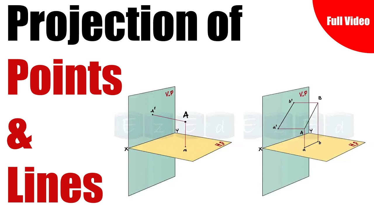
Full Video- Projection Of Points & Lines

Exercise 1.1 Orthographic Drawing
5.0 / 5 (0 votes)