Electrical Engineering: Ch 8: RC & RL Circuits (35 of 65) Step Response of an RL Circuit
Summary
TLDRThis video delves into the step response of RL circuits, where a switch closure leads to a change in current. Initially, no current flows due to the inductor's resistance to change. As time progresses, the current transitions from a transient state to a steady-state value, calculated using Ohm's Law. The video derives the equation for current over time, emphasizing the roles of both transient and steady-state components. This foundational understanding of RL circuit behavior is essential for anyone interested in electrical engineering and circuit analysis.
Takeaways
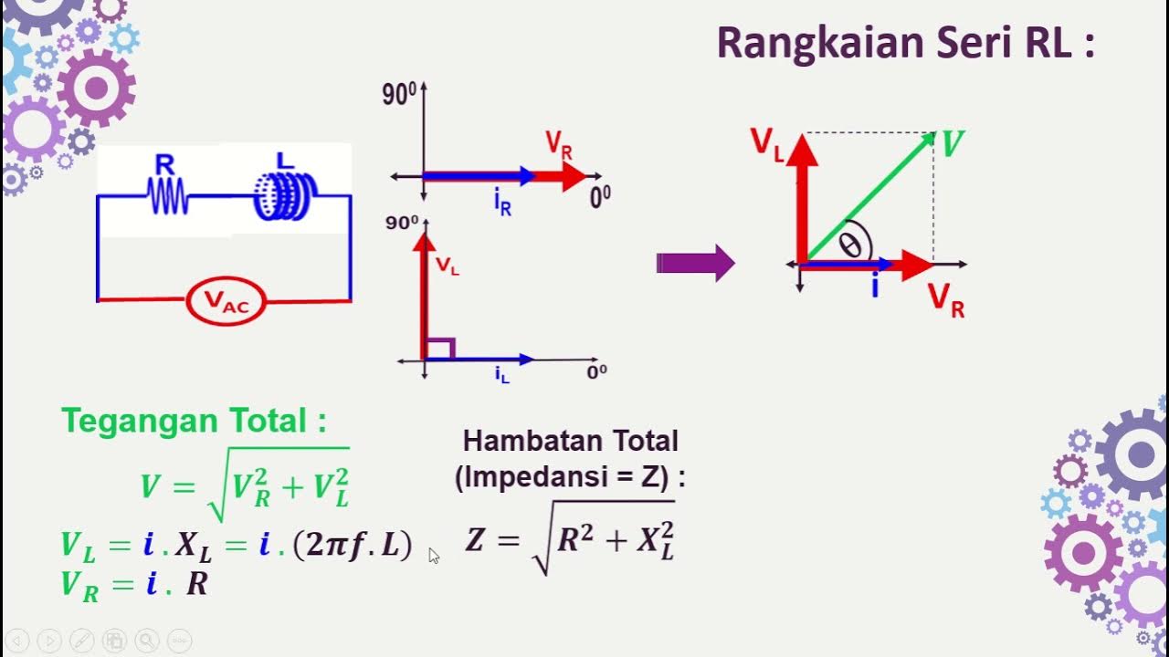
- 😀 An RL circuit consists of a resistor (R) and an inductor (L) connected to a voltage source.
- 🔌 When the switch in the circuit is closed at time t=0, the current begins to flow.
- ⏳ Before the switch closes, there is no current in the circuit due to the inductor's opposition to changes in current.
- 📈 The current in the circuit increases over time, moving towards a steady-state value.
- 📊 The steady-state current can be calculated using Ohm's Law: I_steady = V / R.
- 📉 The transient response of the circuit can be modeled with an exponential function: I(t) = K e^(-t/τ) + I_steady.
- ⚙️ The time constant (τ) of the RL circuit is defined as τ = L / R, indicating how quickly the current changes.
- 📏 At t=0, the initial current can be determined and is crucial for calculating the constant K in the equation.
- 🔍 The complete equation for current as a function of time is I(t) = V/R + (I_initial - V/R)e^(-t/τ).
- 🔄 This equation effectively describes the behavior of current in RL circuits at any point in time.
Q & A
What happens to the current in an RL circuit immediately after the switch is closed?
-Immediately after the switch is closed, there is no current in the circuit because the inductor opposes changes in current.
What is the significance of the time constant (tau) in an RL circuit?
-The time constant (tau) defines how quickly the current in the circuit reaches its steady state and is calculated as tau = L/R, where L is the inductance and R is the resistance.
How is the steady-state current determined in an RL circuit?
-The steady-state current can be calculated using Ohm's Law as I_steady = V/R, where V is the voltage of the source and R is the resistance.
What does the transient portion of the current represent in the context of an RL circuit?
-The transient portion of the current represents the initial behavior of the current as it changes from zero to the steady-state value after the switch is closed.
How is the total current in the RL circuit expressed mathematically?
-The total current in the RL circuit as a function of time is expressed as I(t) = V/R + (I_initial - V/R) * e^(-t/tau).
What does the variable K represent in the current equation?
-The variable K represents a constant that is determined by the initial current in the circuit and can be defined as K = I_initial - V/R.
At what point does the inductor act as a short circuit in an RL circuit?
-The inductor acts as a short circuit once the current has stabilized and there are no longer changes in current, effectively allowing maximum current to flow through the circuit.
Why is it important to add the voltages around the circuit?
-It is important to add the voltages around the circuit to ensure that the sum of the voltages equals zero, which is a fundamental principle of circuit analysis known as Kirchhoff's voltage law.
How can we derive the initial current from the current equation?
-The initial current can be derived from the current equation by evaluating it at t = 0, which gives I(0) = K + V/R.
What happens to the voltage across the inductor as time approaches infinity?
-As time approaches infinity, the voltage across the inductor approaches zero because the current stabilizes, and the inductor no longer opposes changes in current.
Outlines

This section is available to paid users only. Please upgrade to access this part.
Upgrade NowMindmap

This section is available to paid users only. Please upgrade to access this part.
Upgrade NowKeywords

This section is available to paid users only. Please upgrade to access this part.
Upgrade NowHighlights

This section is available to paid users only. Please upgrade to access this part.
Upgrade NowTranscripts

This section is available to paid users only. Please upgrade to access this part.
Upgrade NowBrowse More Related Video

Rangkaian Seri RL-RC-LC dengan Sumber AC

Electrical Engineering: Ch 8: RC & RL Circuits (1 of 43) RC & RL Circuits Introduction

Electrical Engineering: Ch 8: RC & RL Circuits (13 of 43) Current=? in RL Circuit: Ex. 1

Electric Circuits: Basics of the voltage and current laws.

Types Of Circuits | Series Circuit | Parallel Circuit | Electricity UNIT(PART-5) | Grade-7,8

RC and RL Circuits
5.0 / 5 (0 votes)