MODUL1 PENYEARAH 1PHASE (HALF WAVE DAN FULL WAVE) MENGGUNAKAN SIMULINK MATLAB
Summary
TLDRIn this presentation, Muhammad Hafid Alfansyah explains the operation of half-wave and full-wave rectifiers using resistor and capacitor loads. The half-wave rectifier setup involves a 220V AC source, a linear transformer, and a diode, producing a 35.01V DC output. The full-wave rectifier setup, with a transformer set to 6V secondary windings, two diodes, and a capacitor, results in a 3.875V DC output. The video highlights key measurements like RMS voltage, current, and the waveforms produced by each rectification method, demonstrating the impact of circuit components on voltage and current outcomes.
Takeaways
- 😀 The script explains the operation of half-wave and full-wave rectifier circuits with a resistive load.
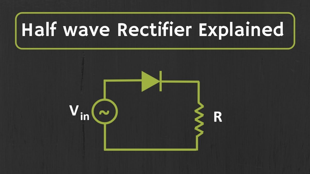
- 😀 Components needed for the half-wave rectifier include a voltage source, linear transformer, diode, and resistor (100 ohms).
- 😀 The half-wave rectifier circuit operates with a 220V AC input, producing 77.78V RMS input voltage and 55V RMS output voltage.
- 😀 The DC output voltage for the half-wave rectifier is 35.01V, with a current of 0.55A.
- 😀 The waveform for the half-wave rectifier is a half-wave form, with the input being sinusoidal and the output showing a peak voltage of 110V.
- 😀 In the full-wave rectifier, a three-winding transformer is used, with a 220V AC input and secondary windings of 6V.
- 😀 The full-wave rectifier utilizes two diodes for rectification, compared to the one diode used in the half-wave rectifier.
- 😀 The capacitor in the full-wave rectifier circuit is 10 µF, and the resistor is 100 ohms.
- 😀 The full-wave rectifier circuit produces 4.243V RMS input voltage and 4.253V RMS output voltage, with a DC output of 3.875V.
- 😀 The current in the full-wave rectifier is 0.034A, and the waveform displays a smooth, full-wave form due to the capacitor's behavior.
- 😀 The key difference between half-wave and full-wave rectifiers is the diode configuration and the smoother output provided by the full-wave rectifier.
Q & A
What is the main topic of the script?
-The main topic of the script is about the explanation of half-wave and full-wave rectification circuits with resistive loads, including the components and measurements involved.
What components are required for the half-wave rectification experiment?
-The components needed for the half-wave rectification experiment include an AC voltage source, a linear transformer, a diode, a resistor, a current measurement tool, and a voltage measurement tool.
What is the purpose of setting the linear transformer to specific windings?
-The purpose of setting the linear transformer to specific windings is to achieve the required input and output voltages. For example, the primary winding is set to 220V, and the secondary winding is set to 110V.
What is the significance of using a 100 ohm resistor in the circuit?
-The 100 ohm resistor is used to limit the current flowing through the circuit, helping to control the power dissipation and ensuring safe operation of the circuit.
What were the measured RMS values for input and output voltages during the half-wave experiment?
-In the half-wave experiment, the RMS value for the input voltage was 77.78V, and the RMS value for the output voltage was 55V.
What type of waveform does the output voltage have in the half-wave rectification?
-The output voltage in the half-wave rectification forms a half-wave pattern with a peak voltage of 110V.
How does the current behave in the half-wave rectification circuit?
-In the half-wave rectification circuit, the current has an RMS value of 0.55A, and the DC current is measured at 0.3501A.
What changes in the full-wave rectification setup compared to the half-wave setup?
-In the full-wave rectification setup, two diodes are used instead of one, and a capacitor is added to the RLC branch. The transformer is set with three windings to achieve a different voltage configuration.
What are the key differences in the waveforms between half-wave and full-wave rectification?
-The half-wave rectified waveform shows a single half-cycle, while the full-wave rectified waveform alternates through the entire cycle, with the capacitor helping smooth out the output.
What were the measured RMS values for input and output voltages in the full-wave rectification experiment?
-In the full-wave rectification experiment, the RMS voltage for input was 4.243V, and the output RMS voltage was 4.253V. The DC voltage was measured at 3.875V.
Outlines

This section is available to paid users only. Please upgrade to access this part.
Upgrade NowMindmap

This section is available to paid users only. Please upgrade to access this part.
Upgrade NowKeywords

This section is available to paid users only. Please upgrade to access this part.
Upgrade NowHighlights

This section is available to paid users only. Please upgrade to access this part.
Upgrade NowTranscripts

This section is available to paid users only. Please upgrade to access this part.
Upgrade NowBrowse More Related Video


5.0 / 5 (0 votes)