Operational Amplifiers - Inverting & Non Inverting Op-Amps
Summary
TLDRThis video delves into operational amplifiers (op-amps), explaining their function as high-gain differential amplifiers. It outlines the basics of the 741 op-amp, detailing its pin configuration and the significance of input and output impedances. The video explores inverting and non-inverting amplifier circuits, illustrating how to calculate closed-loop voltage gain and emphasizing the role of feedback resistors. It also touches on the importance of slew rate in high-frequency applications, providing an example problem to demonstrate these concepts.
Takeaways
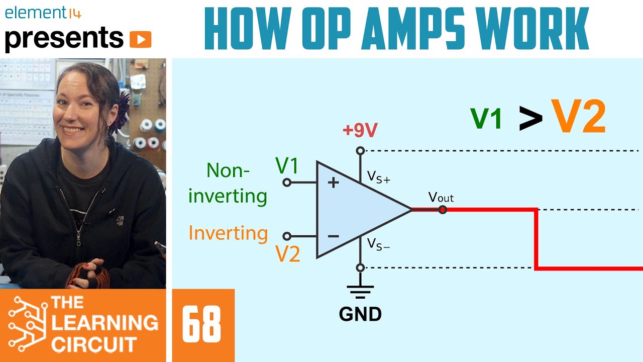
- 🔬 An op-amp (operational amplifier) is a high-gain differential amplifier that amplifies the difference between two input voltages, V1 and V2.
- 🔌 Op-amps have a very high input impedance and a very low output impedance, which is important for circuit design.
- 🔄 The negative terminal of an op-amp is the inverting input, and applying a signal here results in an output signal that is 180 degrees out of phase.
- 🔀 The positive terminal is the non-inverting input, and signals applied here produce an output signal in phase with the input.
- 💡 The 741 is a common type of operational amplifier, with pin 2 as the inverting input, pin 3 as the non-inverting input, and pin 6 as the output.
- 🔋 Pins 4 and 7 of the 741 op-amp are used for the power supply, connecting to batteries or other voltage sources.
- 🔩 The offset null pins (1 and 5) can be used to adjust the output offset voltage to zero, compensating for any inherent bias in the op-amp.
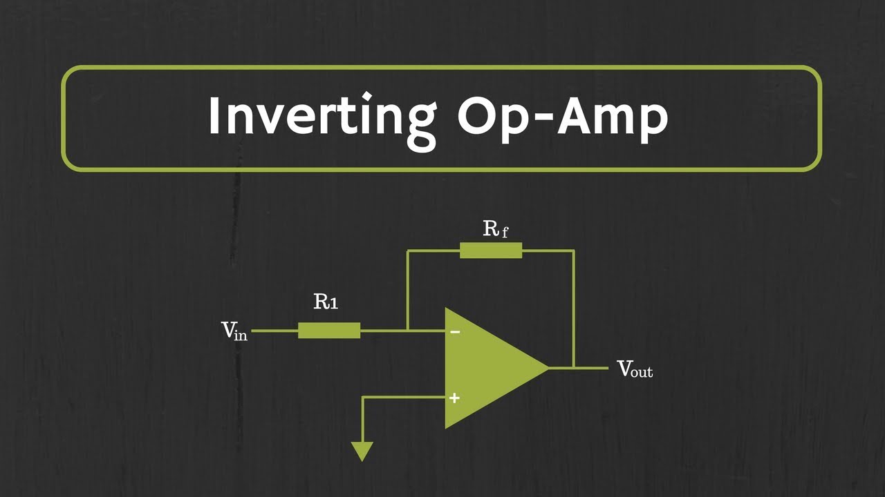
- ⚙️ In an inverting amplifier circuit, the feedback resistor (Rf) is used to create a closed-loop voltage gain, calculated as Rf divided by the input resistor (Rn).
- 🔄 Removing the feedback resistor puts the op-amp in open-loop mode, which has a much higher voltage gain, typically up to 200,000.
- 🔌 Connecting batteries to an op-amp involves setting the ground between the positive and negative terminals of the batteries, with pin 7 connected to the negative terminal and pin 4 to the positive.
- 📈 The slew rate of an op-amp, which is its ability to respond to rapid changes in input signal, is crucial for high-frequency applications and affects the maximum operating frequency.
Q & A
What does 'op amp' stand for and what is its primary function?
-An 'op amp' stands for operational amplifier. Its primary function is to amplify the difference between two input voltages, v1 and v2, with a high gain.
What are the characteristics of an op amp's input and output impedance?
-An op amp has a very high input impedance and a very low output impedance.
How does applying a signal to the inverting input affect the output signal of an op amp?
-Applying a signal to the inverting input of an op amp will result in an output signal that is 180 degrees out of phase with the input signal.
What is the purpose of the feedback resistor (rf) in an op amp circuit?
-The feedback resistor (rf) in an op amp circuit takes a portion of the output signal and feeds it back to the input, which helps to reduce the voltage gain.
How is the closed-loop voltage gain calculated in an inverting amplifier circuit?
-The closed-loop voltage gain in an inverting amplifier circuit is calculated as the feedback resistor (rf) divided by the input resistor (rn), with a negative sign indicating inversion.
What is the significance of the output offset voltage in an op amp?
-The output offset voltage is the voltage that an operational amplifier can generate at its output even when there is no input signal. It can be adjusted to zero using the offset null pins.
What is the typical open-loop voltage gain of an op amp?
-The typical open-loop voltage gain of an op amp, represented by g_sub_v, could be as high as 200,000.
How should batteries be connected to an op amp for power supply?
-Batteries should be connected in series with the positive terminal of one battery connected to pin 4 of the op amp and the negative terminal of the other battery connected to pin 7, with the ground in between.
What is the difference between an inverting and a non-inverting amplifier circuit?
-In an inverting amplifier, the input signal is applied to the inverting input, and the output signal is out of phase with the input. In a non-inverting amplifier, the input signal is applied to the non-inverting input, and the output signal is in phase with the input.
How is the closed-loop voltage gain calculated for a non-inverting amplifier circuit?
-For a non-inverting amplifier circuit, the closed-loop voltage gain is calculated as the feedback resistor (rf) divided by the input resistor (rn), but with an additional '1' added to the result.
What is the slew rate and why is it important in op amp circuits?
-The slew rate is a measure of how quickly the output of an op amp can change in response to a change in input voltage. It's important because it affects the maximum operating frequency of the op amp and the ability to accurately amplify high-frequency signals.
Outlines

This section is available to paid users only. Please upgrade to access this part.
Upgrade NowMindmap

This section is available to paid users only. Please upgrade to access this part.
Upgrade NowKeywords

This section is available to paid users only. Please upgrade to access this part.
Upgrade NowHighlights

This section is available to paid users only. Please upgrade to access this part.
Upgrade NowTranscripts

This section is available to paid users only. Please upgrade to access this part.
Upgrade NowBrowse More Related Video


5.0 / 5 (0 votes)