Proses pengisian dan pengeluaran daya pada kapasitor
Summary
TLDRIn this educational video, Muhammad Syarif and Putri Maharani explain the charging and discharging processes of a capacitor. They describe how a capacitor initially acts as an open circuit, allowing current to flow as voltage increases, and then as a closed circuit when fully charged. The discharging process is demonstrated by connecting the charged capacitor to a resistor, causing the voltage to decrease over time. The tutorial also includes a practical demonstration using a simulation tool, showing the time it takes for a 3V capacitor to charge and a 12V capacitor to discharge. The video is an informative guide for understanding capacitors' role in electronic applications such as energy storage, signal filtering, and timing in electrical circuits.
Takeaways
- 🔋 The process of charging and discharging a capacitor is fundamental in electronic circuits.
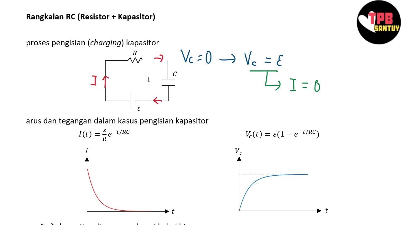
- ⚡️ When a voltage is first applied to an initially uncharged capacitor, the current is at its maximum and then decreases over time as the voltage across the capacitor increases.
- 🔌 At full charge, the voltage across the capacitor equals the source voltage, and the capacitor acts as an open circuit with no current flowing.
- 🔌 To discharge a capacitor, it can be connected to a load, such as a resistor, which causes the current to flow through the resistor and the voltage across the capacitor to decrease.
- ⏲️ The discharging process continues until the voltage across the capacitor reaches zero, signifying that the capacitor is empty.
- 🔧 Capacitors are used in various electronic applications including energy storage, signal filtering, and timing in electrical circuits.
- 🛠️ The tutorial demonstrates how to set up a circuit for charging and discharging a capacitor, including the use of a DC voltage source and a resistor.
- 📏 A DC voltmeter is used to measure the voltage across the capacitor during the charging process, indicating the rise in voltage.
- ⏱️ The tutorial provides an example of the time it takes for a capacitor to charge to a certain voltage and the time required for it to discharge.
- 🔄 The tutorial also includes instructions on how to change component values and names in a simulation environment to understand the effects of different resistor values on the charging and discharging times.
- 👨🏫 The presenters, Muhammad Syarif and Putri Maharani, conclude the tutorial with a friendly acknowledgment of their contributions to the material.
Q & A
What is the purpose of the tutorial mentioned in the script?
-The purpose of the tutorial is to explain the process of charging and discharging energy in a capacitor.
How does a capacitor initially behave when a voltage is applied?
-Initially, when voltage is applied to a capacitor, it acts as an open circuit, allowing the maximum current to flow through it as the voltage across the capacitor increases over time.
What happens to the current and voltage in a capacitor during charging?
-During charging, the voltage across the capacitor increases while the current decreases until the capacitor is fully charged, at which point the voltage equals the source voltage and the current becomes zero.
How is a capacitor discharged?
-A capacitor is discharged by connecting it to a circuit, such as a resistor, which allows the current to flow through the resistor and the voltage across the capacitor to decrease over time.
What is the final state of a capacitor after it has been fully discharged?
-After a capacitor has been fully discharged, its voltage reaches 0, and it returns to an empty state.
What are the various applications of capacitors in electronic devices?
-Capacitors are used in various electronic applications such as energy storage, signal filtering, and timing adjustments in electrical circuits.
What components are used in the circuit for charging and discharging a capacitor as described in the script?
-The circuit for charging and discharging a capacitor includes a DC power source, a switch, a capacitor, and a resistor for discharging.
Why is it recommended to use a toggle switch in the circuit?
-A toggle switch is recommended to easily control the connection and disconnection of the capacitor to the charging and discharging circuits.
What is the role of a DC voltmeter in the circuit described?
-A DC voltmeter is used to indicate the increase in voltage across the capacitor during the charging process.
How can one observe the charging and discharging processes in the tutorial?
-The tutorial uses a simulation where one can observe the charging and discharging processes by noting the time required for the capacitor to charge or discharge to a certain voltage level.
What is the significance of the time recorded during the simulation?
-The time recorded during the simulation is significant as it helps to understand the rate at which the capacitor charges or discharges, which is influenced by the resistor's value.
Outlines

This section is available to paid users only. Please upgrade to access this part.
Upgrade NowMindmap

This section is available to paid users only. Please upgrade to access this part.
Upgrade NowKeywords

This section is available to paid users only. Please upgrade to access this part.
Upgrade NowHighlights

This section is available to paid users only. Please upgrade to access this part.
Upgrade NowTranscripts

This section is available to paid users only. Please upgrade to access this part.
Upgrade NowBrowse More Related Video

Rangkaian RC (Resistor-Kapasitor) | Rangkaian DC | Part 5 | Fisika Dasar

Capacitor Explained : Calculations | Series | Parallel | Charging | Discharging

Elektronika Dasar 006 Capasitor 02 Universitas Jember

charging and discharging of capacitor working model | Physics Project for class 12

Positive & Negative Clamper Circuits

Boost Your RC Circuit Analysis Skills with an Oscilloscope Lab
5.0 / 5 (0 votes)