Automatic Plant Watering System using Arduino & Soil Moisture Sensor | LCD display [with CODE]
Summary
TLDRThis Arduino tutorial video builds on a previous lesson about soil moisture sensors by integrating an LCD module and a water pump to create an automatic plant watering system. The required components include an Arduino board, soil moisture sensor, LCD module, relay module, a 9-volt water pump, and jumper wires. The script outlines the connections for each part and provides a code example that activates the pump when soil is dry, displaying status on the LCD. The demonstration shows the system in action, automatically watering the plant when needed.
Takeaways
- 😀 The video is an Arduino tutorial focused on creating an automatic plant watering system.
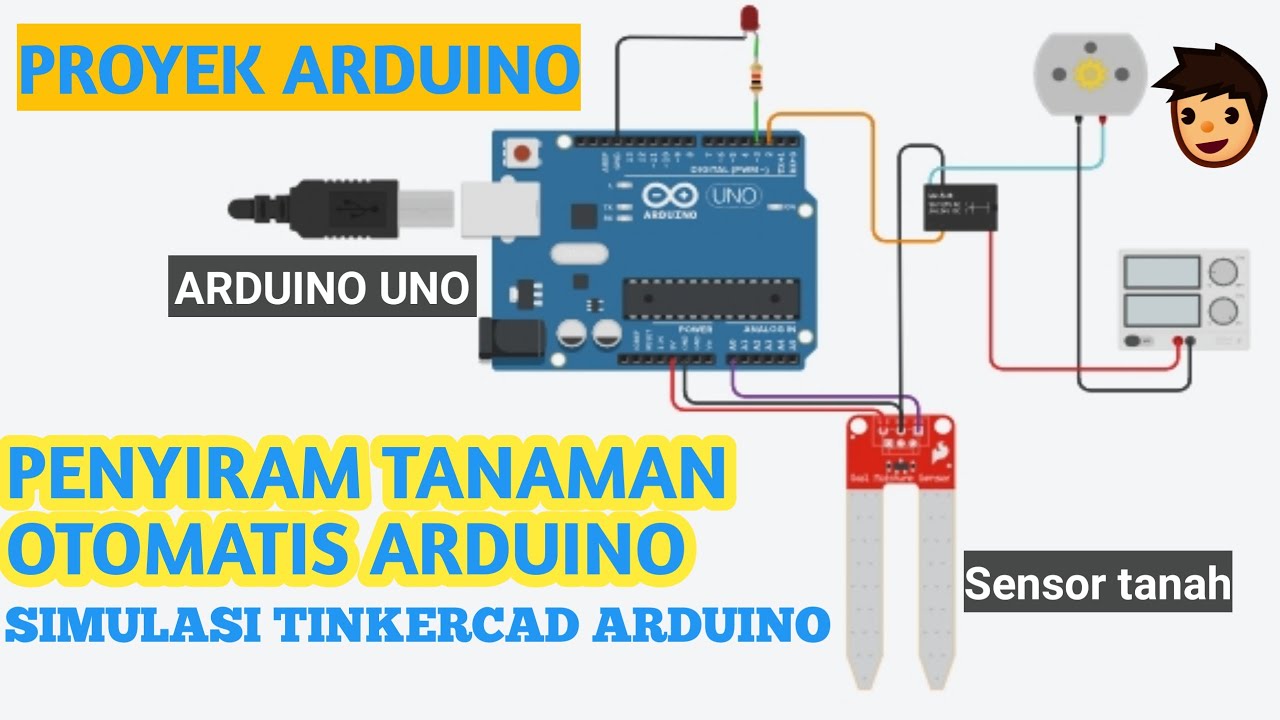
- 🔧 The main components needed are an Arduino board, a soil moisture sensor, an LCD module, a relay module, a water pump, and jumper wires.
- 📐 The LCD module used is a 16x2 I2C model, which simplifies the wiring process.
- 🔌 Connections involve linking the VCC and ground of all components to the Arduino's 5V and ground, with specific pins for the sensor, LCD, and relay.
- 💧 The soil moisture sensor's analog output is connected to Arduino's analog pin A0.
- 🖥 The LCD module's SDA and SCL pins are connected to Arduino's analog A4 and A5 pins, respectively.
- 🔘 The relay module's signal input is connected to a digital pin on the Arduino, in this case, digital pin 7.
- 🌡 The water pump's operation is controlled by the relay module, which is activated when the soil is dry based on sensor readings.
- 📊 The code includes logic to determine soil moisture levels and activate the pump accordingly.
- 💬 The LCD displays the soil moisture status and the motor's (pump's) status.
- 🔧 A demonstration is provided showing the system in action, with the pump turning on when the soil is dry and off when it's wet.
Q & A
What is the main focus of the video tutorial?
-The main focus of the video tutorial is to demonstrate how to add an LCD module and a water pump to an existing soil moisture sensor setup to create an automatic plant watering system using an Arduino board.
What is the purpose of using an LCD module in this project?
-The purpose of using an LCD module is to display the moisture content of the soil, providing a visual representation of the sensor readings.
What type of water pump is used in the tutorial?
-A small 9-volt water pump is used in the tutorial for the automatic plant watering system.
What is the role of the relay module in this setup?
-The relay module is used to control the water pump's operation based on the soil moisture levels read by the sensor.
Which pins on the Arduino board are used for the LCD module connections?
-The LCD module's VCC and ground are connected to the Arduino's 5V and ground. The SDA pin is connected to the Arduino's analog A4 pin, and the SCL pin is connected to the Arduino's analog A5 pin.
How is the soil moisture sensor connected to the Arduino board?
-The soil moisture sensor's VCC and ground are connected to the Arduino's 5V and ground, and the analog output pin is connected to the Arduino's analog pin A0.
What is the significance of the value 950 in the code?
-The value 950 is used as a threshold in the code to determine when the soil is dry and needs watering, triggering the relay to activate the water pump.
How does the code differentiate between dry, medium, and wet soil conditions?
-The code uses if-else statements to evaluate the sensor values. If the value is greater than 950, the soil is considered dry. If the value is between a certain range (not specified in the transcript), the soil is medium. If less than 400, it is considered wet.
What function is used to control the relay pin in the code?
-The `digitalWrite` function is used to control the relay pin, which is connected to digital pin 7, to turn the water pump on or off based on the soil moisture levels.
How is the status of the soil and the motor displayed on the LCD?
-The status of the soil (dry, medium, wet) and the motor status (on or off) are displayed on the LCD using the LCD module's commands, with the soil status on the first row and the motor status on the second row.
What is the purpose of the demonstration at the end of the tutorial?
-The purpose of the demonstration is to show the automatic plant watering system in action, illustrating how the system monitors soil moisture and triggers the water pump when the soil is dry.
Outlines

This section is available to paid users only. Please upgrade to access this part.
Upgrade NowMindmap

This section is available to paid users only. Please upgrade to access this part.
Upgrade NowKeywords

This section is available to paid users only. Please upgrade to access this part.
Upgrade NowHighlights

This section is available to paid users only. Please upgrade to access this part.
Upgrade NowTranscripts

This section is available to paid users only. Please upgrade to access this part.
Upgrade NowBrowse More Related Video
Sistem penyiraman tanaman otomatis esp8266 (BLYNK)

Penyiram Tanaman Otomatis Soil Moisture Sensor VLOG118
PROYEK ARDUINO PENYIRAM TANAMAN OTOMATIS DENGAN SENSOR KELEMBABAN TANAH SIMULASI TINKERCAD ARDUINO
Sistema de Irrigação Automática com Arduino e Sensor de Umidade do Solo

How to make Automatic Plant Watering System using Arduino UNO and Soil Sensor || Techie Lagan

PROJECT ARDUINO PENYIRAM TANAMAN OTOMATIS /SMARTGARDEN BERBASIS ARDUINO NANO DAN SENSOR SOILMOISTURE
5.0 / 5 (0 votes)