METODE MATRIKS KEKAKUAN #2, Metode Matriks Kekakuan, Plane Truss Structures, Struktur Rangka Bidang
Summary
TLDRThis tutorial provides a clear, step-by-step guide on structural analysis using the stiffness method, focusing on plane truss and frame structures. It explains determining degrees of freedom, forming local stiffness matrices, transforming them into global coordinates, and assembling the global stiffness matrix. The video demonstrates calculating displacements, internal forces, and support reactions, emphasizing systematic, modular procedures ideal for computer implementation. Practical examples of bridges and frame structures illustrate how to apply transformations, solve linear equations, and obtain structural responses accurately. The tutorial is designed for easy understanding, making complex structural analysis accessible for learners and practitioners alike.
Takeaways
- 😀 The stiffness method is a preferred structural analysis technique because it provides a single, unified solution and is highly structured, making it suitable for computer programming.
- 😀 The first step in the stiffness method is to define the degrees of freedom (DOF) for each node, which determines the size of the stiffness matrices.
- 😀 Each structural node typically has two degrees of freedom in a planar truss: horizontal and vertical displacement.
- 😀 The local stiffness matrix of a member relates forces at its ends to displacements in the local coordinate system, accounting for axial stiffness EA/L.
- 😀 Transformation matrices convert local stiffness matrices to the global coordinate system using trigonometric relationships based on the member's orientation angle.
- 😀 The global stiffness matrix for the entire structure is assembled by summing the contributions of all members, aligned according to the global DOF numbering.
- 😀 Structural displacements are solved from the equation P = K * U, where P is the global force vector, K is the global stiffness matrix, and U is the global displacement vector.
- 😀 Numerical methods such as Gaussian elimination or Gauss-Jordan can be used to solve the system of linear equations for nodal displacements.
- 😀 Internal member forces are calculated by applying the local stiffness matrix to the member's local displacements, after transforming global displacements back to local coordinates.
- 😀 Reactions at supports are determined by transforming local member forces to the global system and subtracting any applied external forces at the support.
- 😀 The method ensures consistency across all members by maintaining a common global coordinate system and using orthogonal transformation matrices.
- 😀 This structured, modular approach allows the stiffness method to handle complex trusses efficiently, providing both member forces and support reactions accurately.
Q & A
What is the main focus of the video tutorial?
-The tutorial focuses on the stiffness (kekakuan) method for structural analysis, particularly for plane frame structures, explaining step-by-step procedures to calculate nodal displacements, member deformations, internal forces, and support reactions.
Why is the stiffness method preferred over the flexibility method?
-The stiffness method is preferred because it provides a single, unique solution, has structured and modular steps, and is easier to implement in computer programs for structural analysis.
How is the degree of freedom (DOF) defined in plane frame structures?
-In plane frame structures, each free nodal point has two degrees of freedom: horizontal displacement (U_x) and vertical displacement (U_y). These DOFs determine the size of the global stiffness matrix.
How is the local stiffness matrix of a member formulated?
-The local stiffness matrix relates axial forces at member ends to their displacements. For a 2D member, it is a 4×4 matrix that accounts for horizontal and vertical displacement components of both ends.
What is the purpose of the transformation matrix in the stiffness method?
-The transformation matrix converts local member displacements and forces to the global coordinate system, allowing all members to be analyzed consistently in a single reference frame.
How is the global stiffness matrix of the structure obtained?
-Each member's local stiffness matrix is transformed to global coordinates, then assembled into the global stiffness matrix according to the member's connected degrees of freedom.
What equation relates nodal displacements to external forces in the stiffness method?
-The relationship is expressed as P = K * U, where P is the vector of external forces, K is the global stiffness matrix, and U is the vector of nodal displacements.
Once nodal displacements are calculated, how are member forces determined?
-Member forces in local coordinates are calculated using S_local = K_local * u_local, where u_local is obtained by transforming the global displacements U to the member's local coordinate system.
How are support reactions computed in this method?
-Support reactions are obtained by transforming local member forces to global coordinates using R = T^T * S_local - P_external, considering only the member ends connected to supports.
What are the main computational steps for analyzing a structure using the stiffness method?
-1) Determine degrees of freedom, 2) Form local stiffness matrices, 3) Transform matrices to global coordinates, 4) Assemble global stiffness matrix, 5) Solve P = K * U for nodal displacements, 6) Compute member deformations and internal forces, 7) Calculate support reactions.
How can the cosine and sine of a member’s angle be calculated without directly measuring the angle?
-Cosine and sine can be calculated from nodal coordinates: cos(α) = (x_j - x_i)/L, sin(α) = (y_j - y_i)/L, where L is the length of the member, and (x_i, y_i) and (x_j, y_j) are the coordinates of the member’s endpoints.
Why is the global stiffness matrix important for computer-based structural analysis?
-The global stiffness matrix consolidates all member stiffnesses in a common coordinate system, allowing efficient numerical solution of large and complex structures using computer programs.
Outlines

Этот раздел доступен только подписчикам платных тарифов. Пожалуйста, перейдите на платный тариф для доступа.
Перейти на платный тарифMindmap

Этот раздел доступен только подписчикам платных тарифов. Пожалуйста, перейдите на платный тариф для доступа.
Перейти на платный тарифKeywords

Этот раздел доступен только подписчикам платных тарифов. Пожалуйста, перейдите на платный тариф для доступа.
Перейти на платный тарифHighlights

Этот раздел доступен только подписчикам платных тарифов. Пожалуйста, перейдите на платный тариф для доступа.
Перейти на платный тарифTranscripts

Этот раздел доступен только подписчикам платных тарифов. Пожалуйста, перейдите на платный тариф для доступа.
Перейти на платный тарифПосмотреть больше похожих видео
ANALISA STRUKTUR 2 MATRIKS KEKAKUAN LANGSUNG BALOK SOAL&PEMBAHASAN#Stiffnessglobalmatrix#matrix
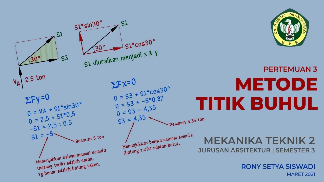
Mekanika Teknik 2 Metode Titik Buhul

Sangat mudah contoh perhitungan rangka batang cara grafis- rangka jembatan
V11.1 Statis Tak Tentu - Force Method untuk Truss System

Stiffness Matrix Method for Analysis of Beams ( With Overhanging )
SAP 2000 - Analisa Struktur Baja (SNI)
5.0 / 5 (0 votes)
