Robotic Arm with Arduino - Save/Play/Export/Import Positions.
Summary
TLDRThis video provides a step-by-step guide on building a 3D-printed robotic arm powered by an Arduino and servo motors. The arm can be controlled through an interface, allowing users to save, replay, and export programmed positions. The creator walks through the design, assembly, and coding process, offering downloadable files for customization. The project uses multiple servos for different joints and a claw, all integrated with Arduino. The video also explains how to control the arm using a custom application, showcasing features like speed control and movement replay. It's a hands-on, innovative project for robotics enthusiasts.
Takeaways
- 🤖 The video shows how to make a 3D printed robotic arm controlled by Arduino and servo motors.
- 💻 The arm can be controlled through an interface that allows saving, replaying, exporting, and importing movements.
- 🖱️ The 3D model of the arm was designed and simulated before being brought to reality, and the video includes links for downloading the necessary files.
- 🔧 The assembly starts with soldering a DC jack socket and connecting it to the Arduino, which is then secured to the base.
- 🔩 Multiple servo motors (mg995 and mg90s) are used to control various parts of the robotic arm, including the base, forearm, and claw.
- 🛠️ Servos must be set to a neutral position (90°) before assembly to ensure smooth operation.
- 🔌 The robotic arm is powered by a 5V 3-amp adapter connected to the Arduino through the DC jack.
- 🎮 The graphical interface for controlling the arm was developed using Processing, and users can manually control the arm or save and replay movements.
- 📁 The interface includes options to export and import saved positions, allowing movements to be reused.
- ⚙️ The entire project, including code for the Arduino and interface, is available in the video description for customization and modification.
Q & A
What is the main purpose of the video?
-The video shows how to create a 3D-printed robotic arm using Arduino and Servo Motors, with features like saving, replaying, exporting, and importing programmed positions.
What software and hardware are used to control the robotic arm?
-The robotic arm is controlled using an Arduino Uno and Servo Motors, along with a graphical interface created with Processing software.
What can be done through the interface mentioned in the video?
-The interface allows manual control of the robotic arm's movements through sliders, saving and replaying movements, controlling speed, and exporting/importing saved positions.
How is the robotic arm powered?
-The robotic arm is powered by a 5V, 3-amp adapter with a DC jack connector.
What file formats are available for downloading the 3D-printed parts?
-The 3D-printed parts are available in Step format for modification and STL format for direct printing.
What should be done before assembling the Servo motors?
-All Servo motors must be set to their neutral position (90°) before assembly.
What is the role of the Arduino in this project?
-The Arduino is responsible for controlling the Servo Motors by sending commands that specify which Servo to move and to what angle, through serial communication.
How are the servos connected to the Arduino?
-The servos are connected to the Arduino's power and digital pins, following a provided wiring diagram.
What additional steps are needed to assemble the robotic arm's claw mechanism?
-The claw mechanism is assembled using plastic adapters, M3 screws, self-locking nuts, and is connected to an mg90s Servo. The cables are threaded through the arm conduit.
What customization options are available for the robotic arm?
-The video offers the ability to modify the design files in Step format, as well as modify the control code through Processing. Viewers are encouraged to contribute suggestions or modifications to the project.
Outlines

Этот раздел доступен только подписчикам платных тарифов. Пожалуйста, перейдите на платный тариф для доступа.
Перейти на платный тарифMindmap

Этот раздел доступен только подписчикам платных тарифов. Пожалуйста, перейдите на платный тариф для доступа.
Перейти на платный тарифKeywords

Этот раздел доступен только подписчикам платных тарифов. Пожалуйста, перейдите на платный тариф для доступа.
Перейти на платный тарифHighlights

Этот раздел доступен только подписчикам платных тарифов. Пожалуйста, перейдите на платный тариф для доступа.
Перейти на платный тарифTranscripts

Этот раздел доступен только подписчикам платных тарифов. Пожалуйста, перейдите на платный тариф для доступа.
Перейти на платный тарифПосмотреть больше похожих видео
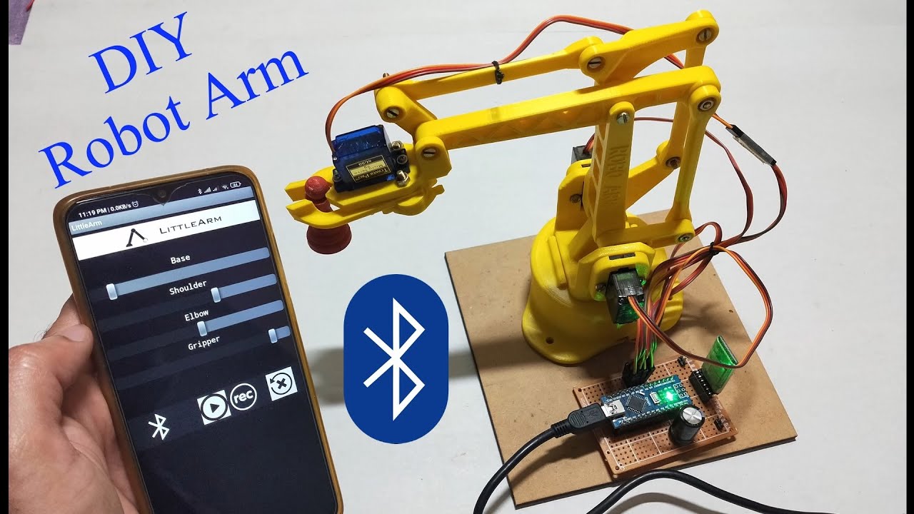
DIY | Smartphone (Bluetooth) controlled Robot Arm using Arduino | HC-05
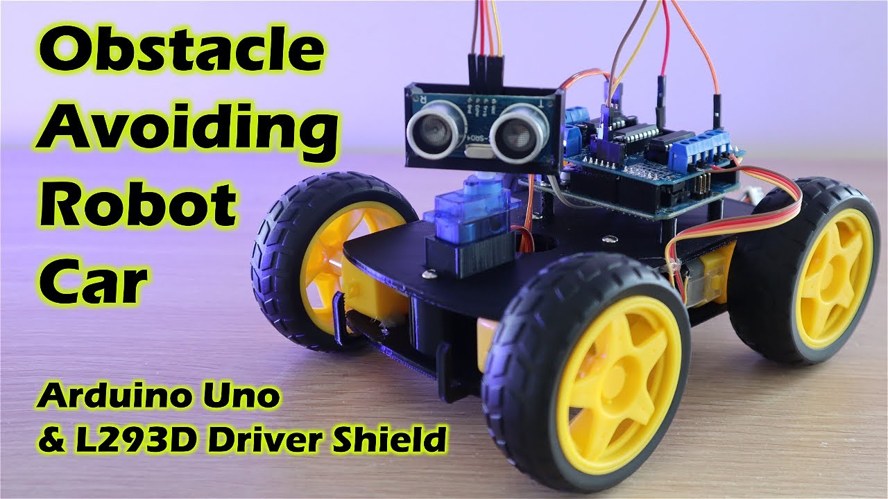
Obstacle Avoiding Robot Car Using An Arduino
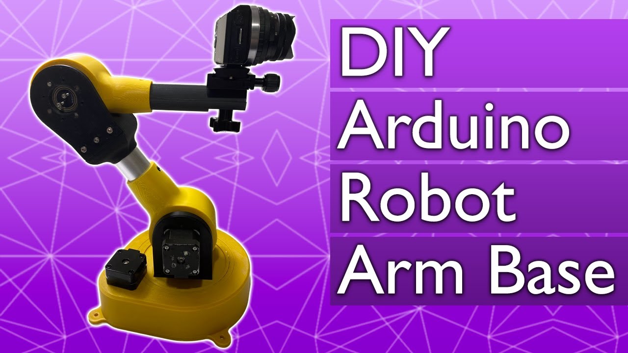
The easiest way to make a robot arm base
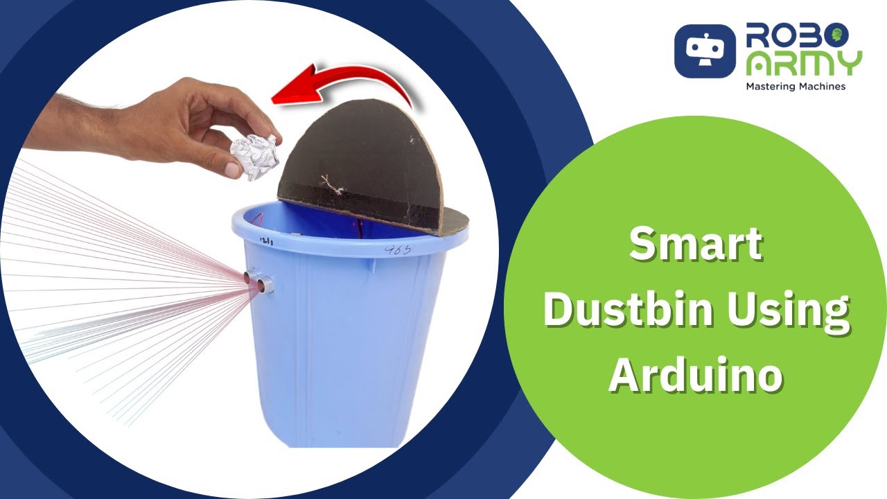
Waste Wizard: Crafting a Smart Dustbin using Arduino UNO I Robo Army I Arduino Basic
Dijamin Bisa | Membuat Kotak Sampah Otomatis

Project Membuat Palang pintu otomatis Jalan tol
5.0 / 5 (0 votes)
