Quiz Buzzer Circuit for Eight players using IC 74LS373 | EE Project
Summary
TLDRIn this video tutorial, viewers learn how to create a quiz competition circuit for eight players using electronic components like the IC 74LS373, LEDs, transistors, and resistors. The presenter walks through the circuit diagram, wiring connections, and the functionality of each component. Demonstrating the circuit's operation, the video highlights how pressing a switch activates the corresponding LED, showcasing player responses in real time. Additionally, the importance of a reset function for the organizer is emphasized, making it an engaging project for electronics enthusiasts looking to build their own quiz system.
Takeaways
- 🎤 The video demonstrates how to create a quiz competition circuit for 8 players using an IC 7 for LS 373.
- 🔌 The circuit includes connections for switches and resistors to manage inputs from the players.
- 💡 Each player has an associated LED to indicate their response in the quiz competition.
- 🛠️ The circuit uses transistors for controlling the output and enabling various functionalities.
- 🔊 A buzzer is included in the circuit to signal events or responses from the players.
- ⚙️ Pull-down resistors (1 kilo-ohm) are used to ensure proper signal grounding for each switch.
- 📊 The circuit incorporates 8 diodes (1N4007) to manage the output to the LEDs.
- 🔄 A reset switch is provided to clear previous inputs and prepare the circuit for the next round.
- 🔋 The circuit operates with a power supply of +6 to +7 volts.
- 🙋♂️ The video encourages viewers to engage by liking, sharing, and subscribing, and invites questions in the comments.
Q & A
What is the primary purpose of the circuit demonstrated in the video?
-The circuit is designed for a quiz competition involving up to eight players, allowing them to submit answers and indicating which player answered.
Which integrated circuit (IC) is used in the quiz competition circuit?
-The circuit uses the 74LS373 IC, which is a latch that can hold data and is used for managing inputs and outputs.
How are the players' switches connected in the circuit?
-Each player's switch is connected to a specific pin on the IC, allowing the circuit to detect which player has pressed their button.
What is the function of the pulldown resistors in the circuit?
-Pulldown resistors ensure that the input pins read a stable low voltage (ground) when the switches are not pressed, preventing floating inputs.
How does the circuit indicate which player's button has been pressed?
-When a player presses their button, the corresponding LED lights up, indicating that the player has submitted an answer.
What role do the transistors play in the circuit?
-Transistors are used to control the buzzer and manage the output signals to the LEDs, allowing for sound and visual feedback when a button is pressed.
How is the reset functionality implemented in the circuit?
-A reset switch is included, which, when pressed, clears the previous selections, resetting the circuit for the next question.
What type of buzzer is used in the circuit, and what does it do?
-A buzzer is connected to the circuit to provide auditory feedback whenever a player presses their button.
How many LEDs are used in the circuit and what is their purpose?
-Eight LEDs are used, with each one corresponding to a player, lighting up to indicate which player has pressed their button.
What voltage range can be supplied to the circuit?
-The circuit can operate with a power supply voltage ranging from 6V to 7V.
Outlines

このセクションは有料ユーザー限定です。 アクセスするには、アップグレードをお願いします。
今すぐアップグレードMindmap

このセクションは有料ユーザー限定です。 アクセスするには、アップグレードをお願いします。
今すぐアップグレードKeywords

このセクションは有料ユーザー限定です。 アクセスするには、アップグレードをお願いします。
今すぐアップグレードHighlights

このセクションは有料ユーザー限定です。 アクセスするには、アップグレードをお願いします。
今すぐアップグレードTranscripts

このセクションは有料ユーザー限定です。 アクセスするには、アップグレードをお願いします。
今すぐアップグレード関連動画をさらに表示

TOP 5 Circuitos Electronicos OPTO Transistor⚡

Best Science Project | Smart Street Project | Inspire Award Project | Smart City Project

cara membaca skema elektronika

Tugas 1, kapasitor sebagai penyimpan muatan listrik

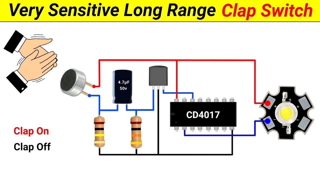
How to make a Clap Switch || using 4017 IC || Very Sensitive Clap Switch || Science Project

How to test electronic components using an avometer
5.0 / 5 (0 votes)
