SAFE - 08 Cracked Section Analysis: Watch & Learn
Summary
TLDRThis tutorial guides users through the SAFE program for cracked section analysis in structural engineering. It explains the automated process for calculating bending moments and curvatures, the iterative method to determine flexural stiffness modifiers, and how to handle both immediate and long-term deflections. The example of a flat slab model demonstrates defining load patterns, assigning loads, and analyzing with different load cases to assess deflections, showcasing the program's capability to handle complex structural analysis.
Takeaways
- 📘 The tutorial covers the use of SAFE program for cracked section analysis, which is crucial for determining bending moments and curvatures in reinforced concrete structures.
- 🔍 SAFE automates the process of finding cracked bending moments and curvatures using an iterative method to adjust flexural stiffness modifiers for each element.
- 🛠️ The initial step involves calculating forces based on elastic properties, and determining reinforcing either by the program or user input.
- 📊 Curvatures for both uncracked and fully cracked states are calculated to find the applied moment's curvature, which helps in computing the flexural stiffness modifier.
- 🔄 The program iterates to adjust bending properties until the change in maximum displacement is minimal, ensuring accuracy in the analysis.
- 📏 SAFE provides options for calculating both immediate and long-term deflections, important for different stages of a structure's life.
- 🏗️ The example model used in the tutorial is a simple two-bay flat slab subjected to various load patterns including dead, superimposed dead, and live loads.
- ⚖️ Load patterns are defined with specific multipliers, and load cases are set up for nonlinear cracked analysis, considering immediate deflections.
- 🔢 The tutorial demonstrates setting up load combinations for displaying elastic deflections and for the analysis of cracked deflections.
- 🔧 Users can specify the source of reinforcement and adjust minimum reinforcing ratios and modulus of rupture within the cracking analysis options.
- 📊 The deformed shape display helps visualize the results of the analysis, showing the deflection changes from elastic to immediate and long-term cracked conditions.
- 🕒 The long-term cracked deflection analysis includes considerations for creep and shrinkage, and involves setting up additional load cases to account for sustained and non-sustained live loads.
Q & A
What is the purpose of the SAFE program mentioned in the tutorial?
-The SAFE program is used to perform a cracked section analysis, determining cracked bending moments and curvatures for every element in a structure.
How does SAFE calculate initial forces in its analysis?
-SAFE calculates initial forces based on elastic properties and the determined reinforcing, either by the program or as input by the user.
What is the iterative process SAFE uses to determine flexural stiffness modifiers?
-The iterative process involves computing interpolation coefficients, determining curvatures for uncracked and fully cracked states, and using a ratio of curvatures to compute a flexural stiffness modifier, which adjusts the bending properties.
What is the significance of the moment-curvature graph shown in the tutorial?
-The moment-curvature graph illustrates the transition between uncracked and fully cracked states, which is crucial for understanding the behavior of elements under different load conditions.
How many options does SAFE offer for calculating cracked deflections?
-SAFE offers two options for calculating cracked deflections: one for immediate deflections and another for long-term deflections.
What is the difference between immediate and long-term deflections in SAFE?
-Immediate deflections are calculated based on service loads without considering time-dependent effects like creep and shrinkage, while long-term deflections account for these effects over time.
How does the tutorial's example model a simple two-bay by two-bay flat slab?
-The model is loaded with three load patterns: dead, superimposed dead, and live loads, and the tutorial demonstrates how to define load patterns, assign loads, and define load cases in SAFE.
What is the purpose of the 'sdead' load pattern in the tutorial?
-The 'sdead' load pattern represents the superimposed dead load and is used to apply a specific load magnitude to the slab in the analysis.
Why are nonlinear load cases used in the tutorial for calculating immediate deflections?
-Nonlinear load cases are used because they allow for the calculation of immediate deflections considering the cracked section behavior, which is not superimposable like linear static load cases.
What are the steps SAFE takes to account for long-term effects like creep and shrinkage in the analysis?
-SAFE sets up additional load cases that include sustained loads with creep and shrinkage, and isolates the immediate deflection component from the non-sustained live load to accurately calculate long-term deflections.
How does SAFE handle the combination of load cases for long-term cracked section analysis?
-SAFE combines the long-term sustained load case with the immediate all loads case, subtracting the immediate sustained case to account for the non-sustained live load component, resulting in a long-term load combination.
Outlines

Cette section est réservée aux utilisateurs payants. Améliorez votre compte pour accéder à cette section.
Améliorer maintenantMindmap

Cette section est réservée aux utilisateurs payants. Améliorez votre compte pour accéder à cette section.
Améliorer maintenantKeywords

Cette section est réservée aux utilisateurs payants. Améliorez votre compte pour accéder à cette section.
Améliorer maintenantHighlights

Cette section est réservée aux utilisateurs payants. Améliorez votre compte pour accéder à cette section.
Améliorer maintenantTranscripts

Cette section est réservée aux utilisateurs payants. Améliorez votre compte pour accéder à cette section.
Améliorer maintenantVoir Plus de Vidéos Connexes
Part Modeling - Inspect Panel, Measure, and Section Analysis

ETABS - 14: Ketidakberaturan Horizontal
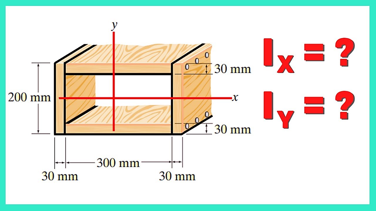
MOMENT OF INERTIA Relative to the X and Y Axes of the Beam Caixão | STATICS
SAP 2000 - Analisa Struktur Baja (SNI)
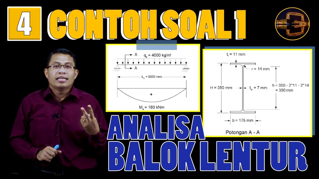
Contoh Perhitungan Analisa Balok Anak dgn Plastik Sempurna (Leleh Umum) | Struktur Baja | Lightboard
EPANET Tutorial 02.07 - Running a Single Period Analysis | Hydraulic Modeling
5.0 / 5 (0 votes)
