SFD and BMD - Problem 1 - Part 1 - Shear Force and Bending Moment Diagram - Strength of Materials
Summary
TLDRThis script details the process of analyzing an overhanging beam's structural behavior under various point loads. It begins with calculating support reactions at points A and B using equilibrium conditions, resulting in RA = 16.71 kN and RB = 32.09 kN. The script then proceeds to determine the shear force diagram (SFD) and bending moment diagram (BMD), crucial for understanding the beam's stress distribution. The SFD reveals varying forces along the beam, while the BMD is essential for identifying the point of contraflexure, a key structural feature. The explanation is technical, targeting an audience with an engineering background.
Takeaways
- 📚 The task involves analyzing a structural engineering problem concerning an overhanging beam with specific support points and loads.
- 🔍 The primary goal is to determine the support reactions at points A and B, which are essential for understanding the beam's stability.
- ⚖️ The equilibrium condition is applied by summing vertical forces (FY) to zero, considering upward forces as positive and downward forces as negative.
- 📐 Moments are calculated about point A, with clockwise moments being positive and anti-clockwise moments negative, to find the reaction force RB.
- 🔢 Through calculations, the reaction force RB is determined to be 32.29 kilo Newtons, which is a critical value for the beam's support.
- 📉 The reaction force RA is then found by subtracting RB from the total vertical force, resulting in RA being 16.71 kilo Newtons.
- 📈 Shear force diagrams (SFD) are to be drawn to visualize how the forces vary along the length of the beam.
- 📍 The sign convention for shear force calculations is established, with upward forces to the left and downward forces to the right considered positive.
- 📉 Shear force at point C is calculated considering the forces and reactions, resulting in a value that remains constant up to point A.
- 🔄 The shear force changes at different sections, such as at point D and B, reflecting the impact of the loads and reactions on the beam's integrity.
- 📝 The final step involves identifying the point of contraflexure, which is a location along the beam where the curvature changes sign, indicating a change in the bending moment.
Q & A
What is the main objective of the script?
-The main objective of the script is to solve a structural engineering problem involving an overhanging beam, which includes determining support reactions at points A and B, drawing the Shear Force Diagram (SFD) and Bending Moment Diagram (BMD), and finding the point of contraflexure.
What are the given point loads on the overhanging beam?
-The given point loads on the overhanging beam are 10 kN at 2 meters from A, 24 kN at 4 meters from A, and 15 kN at 10 meters from A.
What are the equilibrium conditions used to find the support reactions?
-The equilibrium conditions used are the summation of vertical forces (ΣFY) and moments about a point (ΣMA), which are set to zero according to the principles of static equilibrium.
What is the calculated reaction at support A (RA)?
-The calculated reaction at support A (RA) is 16.71 kN.
What is the calculated reaction at support B (RB)?
-The calculated reaction at support B (RB) is 32.29 kN.
How are the moments about point A calculated?
-The moments about point A are calculated by considering the clockwise moments as positive and the anti-clockwise moments as negative, and summing these moments to zero.
What is the sign convention for shear force calculations?
-The sign convention for shear force calculations is that upward forces to the left and downward forces to the right are positive, while downward forces to the left and upward forces to the right are negative.
What is the shear force at point C?
-The shear force at point C is -10 kN, considering the downward force to the left of the section as negative.
How does the shear force change from point A to point D?
-The shear force at point A is +6.71 kN, and it remains constant up to the left of point D. To the right of point D, the shear force becomes -17.29 kN after considering the reactions and loads.
What is the shear force at point B?
-The shear force at point B is +15 kN, which remains constant up to point E.
What is the next step after calculating the support reactions and shear forces?
-The next step after calculating the support reactions and shear forces is to draw the Shear Force Diagram (SFD) and Bending Moment Diagram (BMD), and then find the point of contraflexure.
Outlines

Cette section est réservée aux utilisateurs payants. Améliorez votre compte pour accéder à cette section.
Améliorer maintenantMindmap

Cette section est réservée aux utilisateurs payants. Améliorez votre compte pour accéder à cette section.
Améliorer maintenantKeywords

Cette section est réservée aux utilisateurs payants. Améliorez votre compte pour accéder à cette section.
Améliorer maintenantHighlights

Cette section est réservée aux utilisateurs payants. Améliorez votre compte pour accéder à cette section.
Améliorer maintenantTranscripts

Cette section est réservée aux utilisateurs payants. Améliorez votre compte pour accéder à cette section.
Améliorer maintenantVoir Plus de Vidéos Connexes
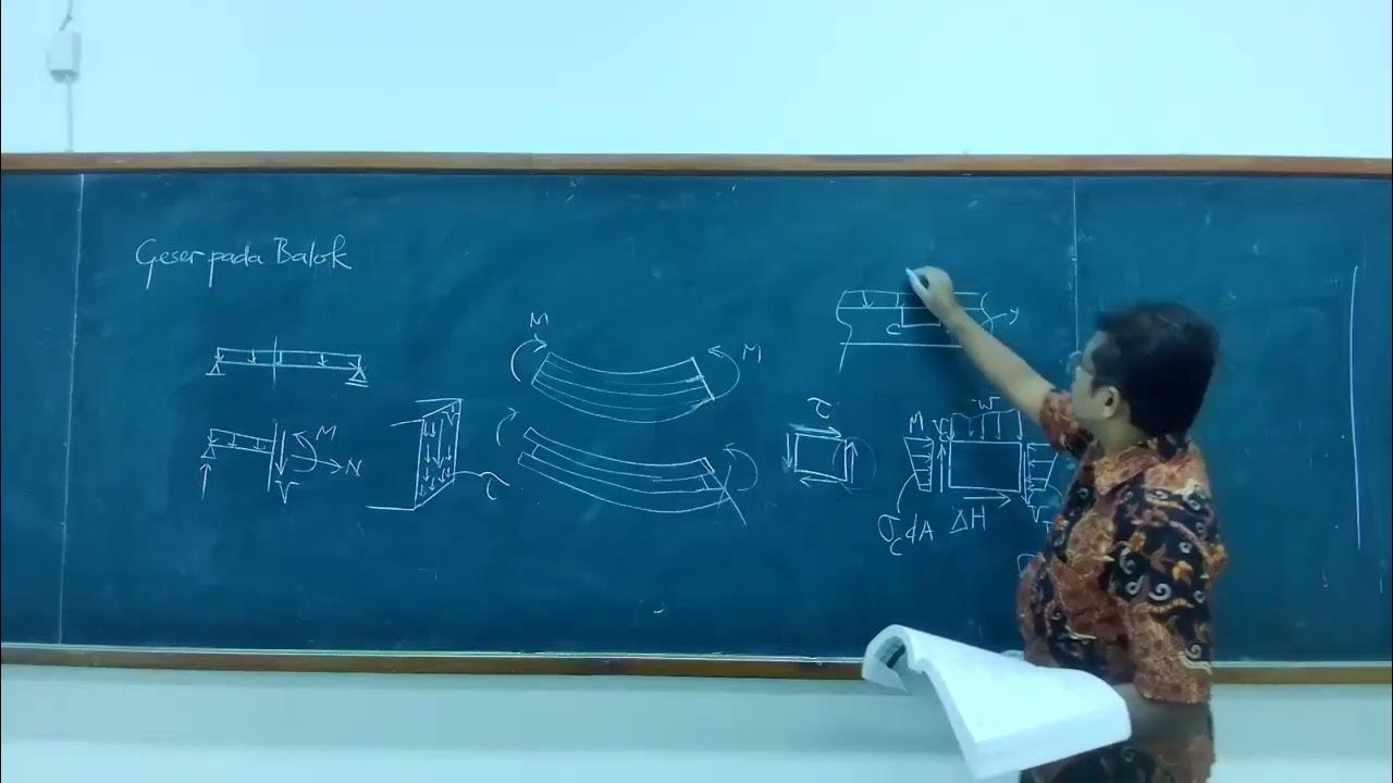
09-05 Tegangan geser pada balok

SAP2000 : Teori Pengantar Struktur Portal & Truss 2D - Hinawan T. Santoso, ST, MT
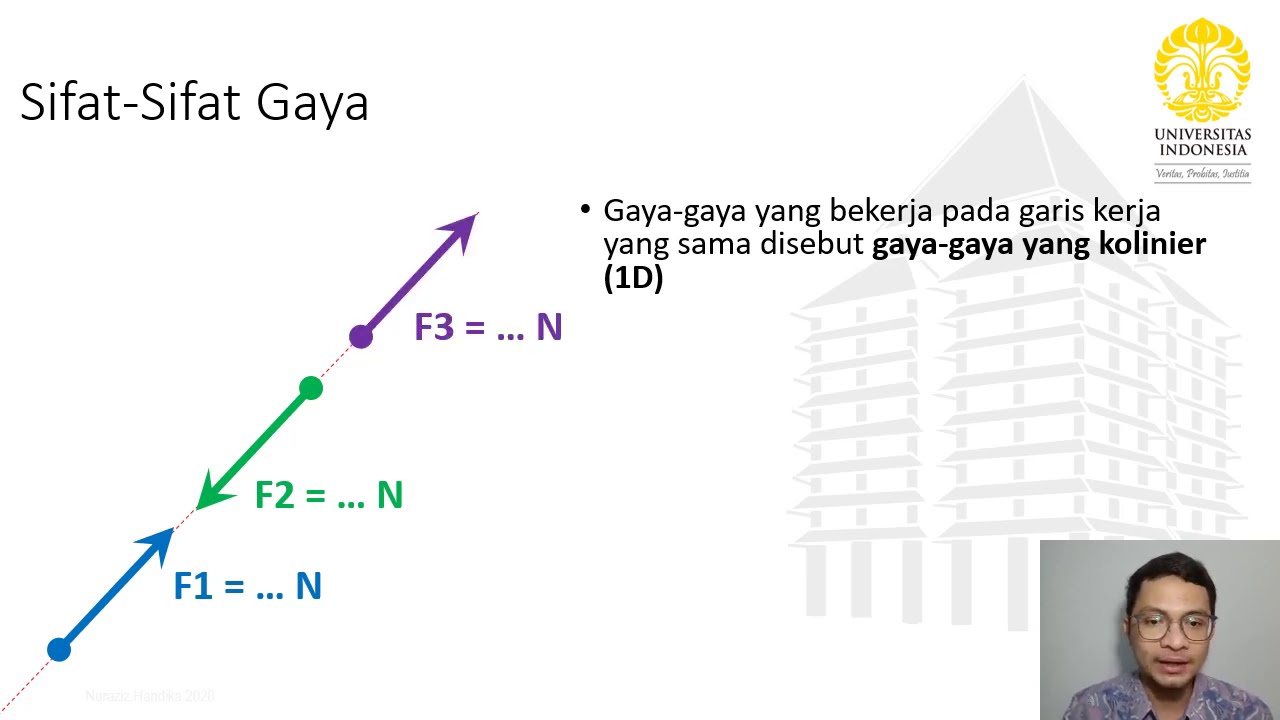
Kuliah Sifat-Sifat Gaya - Statika Kuliah 2(1) Vid

ANALISA STRUKTUR 2 MATRIKS FLEKSIBILITAS SOAL & PEMBAHASAN#Matriksfleksibilitas#Flexibilitymatrix

Pendahuluan hukum dan konsep dasar
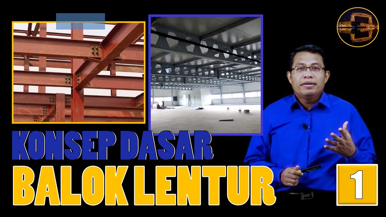
Introduction to Flexural Beam Concept | Steel Structure | Lightboard
5.0 / 5 (0 votes)
