Exercise 1.1 Orthographic Drawing
Summary
TLDRThis tutorial guides viewers through creating an orthographic projection from an isometric drawing. Starting with a 60mm cube, the video walks through the process of drawing the front, top, and side views on paper, using precise measurements, projection lines, and a triangle for vertical alignment. Key steps include labeling views, projecting vertical and horizontal lines, marking dimensions, and applying extension and dimension lines. The tutorial emphasizes the importance of using light lines for projections and provides a clear, step-by-step approach to mastering orthographic and isometric drawing techniques.
Takeaways
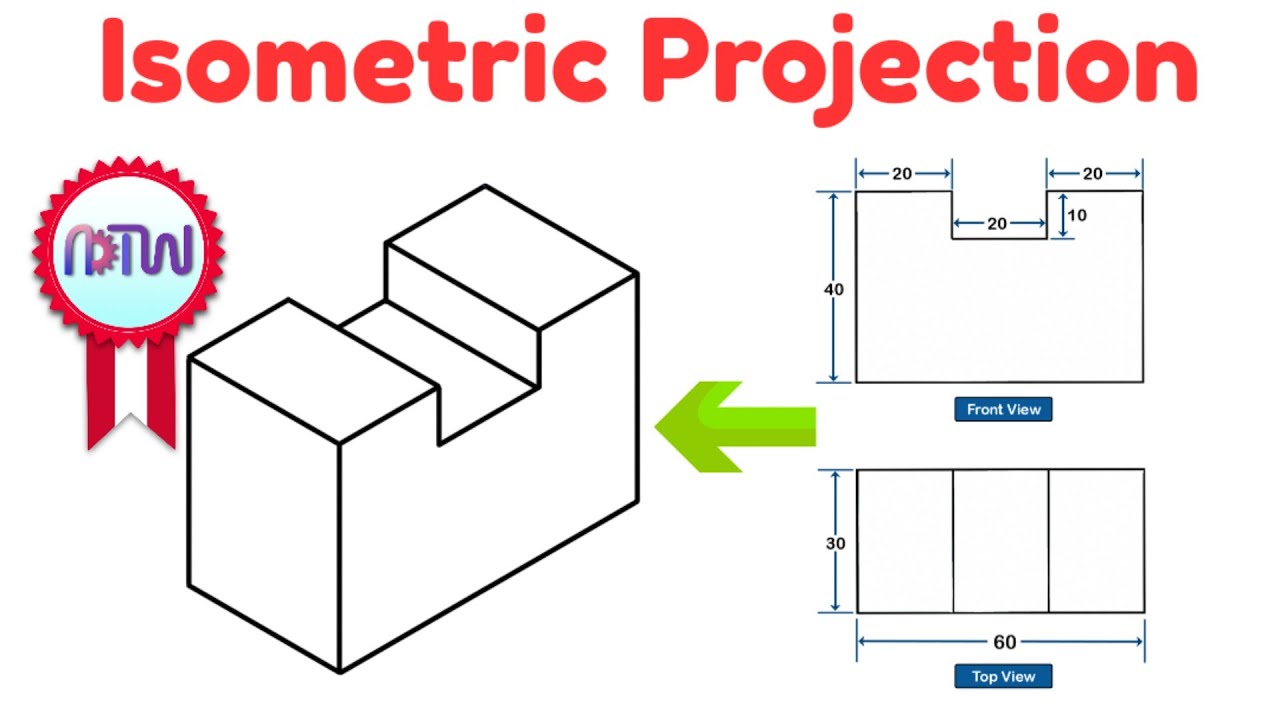
- 😀 Start with an isometric drawing, ensuring it includes all dimensions: width, height, and depth (60mm each). The height of the figure is half of the total height (30mm).
- 😀 Begin constructing the orthographic drawing by first creating a horizontal axis using a T-square.
- 😀 Use a 45° by 90° triangle to establish the vertical axis, ensuring both axes intersect at the center.
- 😀 Mark 10mm spacing above, below, and on both sides of the horizontal axis for clarity in your drawing.
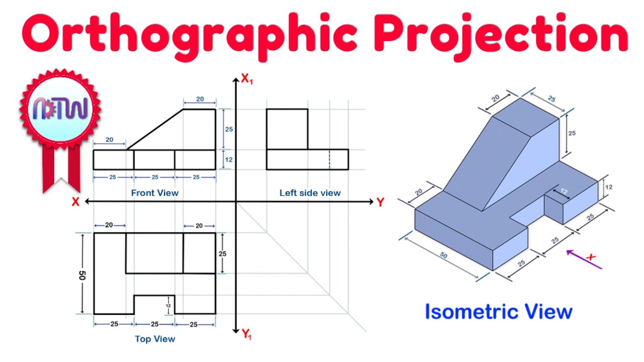
- 😀 Label the three main views of the orthographic drawing: the front view, side view, and top view.
- 😀 To create the front view, measure and mark the height (60mm) and width (60mm), then project the necessary lines from the isometric drawing.
- 😀 For the top view, project vertical lines from the front view downward and measure the width (30mm).
- 😀 For the side view, extend the horizontal lines from the front view and top view to ensure proper alignment.
- 😀 Use light lines for projection and guidelines throughout the drawing process to maintain clarity.
- 😀 Add visible lines after projecting all necessary measurements to define the shape and dimensions in each view.
- 😀 Once the three views are drawn, add dimensions using extension lines, dimension lines, and arrowheads to indicate the exact measurements.
Q & A
What is the purpose of creating an orthographic drawing from an isometric drawing?
-The purpose of creating an orthographic drawing is to represent the object in three views: the front, top, and side views. These views help provide precise, dimensioned illustrations of the object for easier understanding and construction.
What are the three main views of an orthographic drawing?
-The three main views of an orthographic drawing are the front view, the top view, and the side view.
Why is it important to use light lines when drawing projections in an orthographic drawing?
-Light lines are used for projections to ensure that they do not interfere with the visible, final lines. These guidelines are temporary and meant to assist in the layout of the views, without cluttering the final drawing.
What tools are required to begin constructing the orthographic drawing in the script?
-The tools required are a T-square, a 45-degree by 90-degree triangle, and a pencil for making light lines and visible lines.
How are the projection lines used to create the three views in the orthographic drawing?
-Projection lines are drawn from the isometric drawing to the orthographic views (front, top, and side). These lines help translate the measurements from the isometric drawing into each respective view.
How do you determine the height, width, and depth measurements for the orthographic drawing?
-The height, width, and depth are taken directly from the isometric drawing. For example, in the script, the height is 60 mm, the width is 60 mm, and the depth is 60 mm. Dimensions for each view are then calculated based on these measurements.
What is the significance of the 10 mm spaces placed above, below, and to the sides of the horizontal and vertical axes?
-The 10 mm spaces are used to create a margin for the drawing, ensuring that the views have adequate space around them for clarity and to avoid crowding the drawing.
Why is the front view placed on one side, the top view at the bottom, and the side view on the other side in the orthographic drawing?
-This arrangement follows the standard convention in orthographic projection. The front view is placed centrally, with the top and side views positioned relative to it to provide a clear, standardized representation of the object.
What is the purpose of dimension lines and extension lines in an orthographic drawing?
-Dimension lines and extension lines are used to show the exact measurements of an object. Extension lines indicate the limits of the dimension, while dimension lines show the specific size between points, with arrowheads marking the starting and ending points.
How are dimensions placed in the orthographic drawing, and what is the proper procedure for adding them?
-Dimensions are placed by first drawing extension lines from the object to indicate measurement boundaries. Then, dimension lines are added, with arrowheads marking the start and end points. The numerical dimension (e.g., 30 mm) is written between the dimension lines, indicating the size of the feature.
Outlines

Cette section est réservée aux utilisateurs payants. Améliorez votre compte pour accéder à cette section.
Améliorer maintenantMindmap

Cette section est réservée aux utilisateurs payants. Améliorez votre compte pour accéder à cette section.
Améliorer maintenantKeywords

Cette section est réservée aux utilisateurs payants. Améliorez votre compte pour accéder à cette section.
Améliorer maintenantHighlights

Cette section est réservée aux utilisateurs payants. Améliorez votre compte pour accéder à cette section.
Améliorer maintenantTranscripts

Cette section est réservée aux utilisateurs payants. Améliorez votre compte pour accéder à cette section.
Améliorer maintenantVoir Plus de Vidéos Connexes
Orthographic Projection from isometric view in Engineering drawing

Isometric View | How to Construct an Isometric View of an Object
Isometric Projection in Engineering Drawing | isometric projection 3D from orthographic view
Orthographic Projection Explained

ORTHOGRAPHIC DRAWING EXAMPLE

Sectional Drawing/Engineering Drawing N3/Part 1️⃣
5.0 / 5 (0 votes)
