Sectional Drawing/Engineering Drawing N3/Part 1️⃣
Summary
TLDRThis instructional video guides viewers through a detailed process of creating full sectional front and left views using First Angle Orthographic Projection. The presenter walks through key steps such as analyzing cutting planes, dimensions, and angles to construct precise technical drawings. The video emphasizes planning the layout, using appropriate scales, and ensuring accuracy in the placement of components like radii, holes, and sections. Viewers also learn how to handle different projections and measurements, with practical tips for efficient and accurate drawing techniques, all while making complex concepts easy to understand.
Takeaways
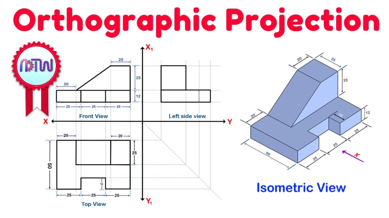
- 😀 The video focuses on drawing full sectional views of a component based on first-angle orthographic projection.
- 😀 The importance of analyzing the given views (front and left) before starting the drawing process is emphasized.
- 😀 The symbols and arrows in the projection (like XX) indicate cutting planes and what is being sectioned.
- 😀 Understanding the dimensions and proper scaling (e.g., scale 1:1) is critical to accurately drawing the views.
- 😀 When creating the front view, it’s important to start by planning the positioning of the views to ensure the top is placed beneath the front view.
- 😀 Accurate measurement is necessary—using tools like a calculator and measuring distances to ensure proper proportions.
- 😀 The use of faint and dark lines helps in showing visible and hidden parts of the component during the drawing process.
- 😀 Radius values, such as 14mm and 22mm, must be marked and drawn accurately, with attention to the scale and proportions.
- 😀 For holes, the diameter and positioning are key—use tools like a stencil ruler for more precise drawing of circular shapes.
- 😀 When performing a sectional cut, it’s crucial to note what is cut and what remains visible, particularly in terms of holes and sections of the component.
- 😀 The video demonstrates how to use the cutting plane to divide the object and explain the parts that are sectioned versus those that are intact.
Q & A
What is the first step when approaching the sectional drawing task?
-The first step is to analyze the two views provided in the question, which are the front and left views in this case. It's crucial to understand the cutting plane and the meaning of the arrows pointing through the component.
How do you determine the cutting plane in the given projection?
-The cutting plane is determined by the arrows marked as 'XX'. These arrows indicate the cutting plane through the component, helping to visualize which part of the object is sectioned and which remains intact.
What does 'full sectional front view' mean in this context?
-A 'full sectional front view' refers to a projection where the component is cut along the designated cutting plane, showing the interior features and details. The word 'full' indicates that a significant portion of the component will be shown in section.
How do you approach setting up the front view in the drawing?
-To set up the front view, first draw faint horizontal and vertical lines to define the boundaries. After measuring dimensions like 92 mm, use the calculated half (46 mm) to place the points and construct the view accurately.
Why is the scale '1:1' important for this drawing?
-The '1:1' scale ensures that the dimensions in the drawing directly correspond to real-life measurements. This means that the component’s size in the drawing will be the same as its actual physical size.
What is the significance of the radius in the drawing process?
-The radius is essential for defining the circular features of the component. In this case, radii of 14 mm, 22 mm, and other measurements are used to correctly place the arcs and circles in the front view and other projections.
What does the term 'faint line' refer to in this context?
-A 'faint line' refers to a light, temporary line used for positioning and alignment in the initial stages of drawing. It helps mark out the framework before finalizing the darker, permanent lines of the drawing.
Why are some dimensions given in halves, such as 46 mm for half of 92 mm?
-Halving dimensions like 46 mm from 92 mm helps in the symmetric placement of features. This method allows for a more balanced and accurate drawing, especially when working with the center of circular features or symmetrical components.
What do the four holes represent in the drawing, and how are they dealt with in the sectional view?
-The four holes are part of the component's design, and their dimensions (diameter 10 mm and 12 mm) are crucial for accurate representation. In the sectional view, some holes are shown in section while others are not, depending on whether they are above or below the cutting plane.
How do you decide whether a hole is shown in section or not?
-A hole is shown in section if it intersects the cutting plane. If the hole is located above or below the cutting plane, it will not appear in the sectional view, but will be represented in its true form in the projection.
Outlines

This section is available to paid users only. Please upgrade to access this part.
Upgrade NowMindmap

This section is available to paid users only. Please upgrade to access this part.
Upgrade NowKeywords

This section is available to paid users only. Please upgrade to access this part.
Upgrade NowHighlights

This section is available to paid users only. Please upgrade to access this part.
Upgrade NowTranscripts

This section is available to paid users only. Please upgrade to access this part.
Upgrade NowBrowse More Related Video
Orthographic Projection from isometric view in Engineering drawing

ORTHOGRAPHIC DRAWING EXAMPLE

Exercise 1.1 Orthographic Drawing
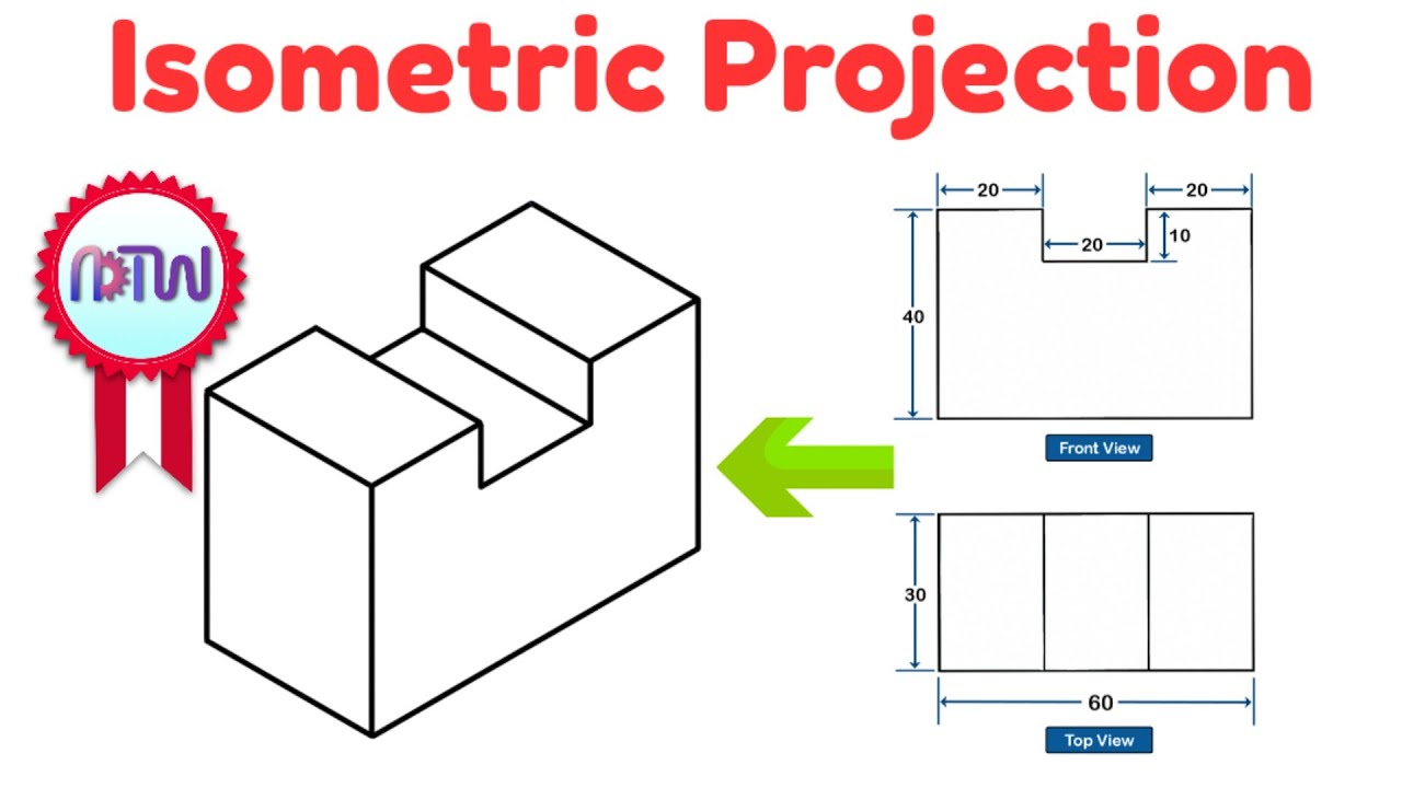
Isometric Projection in Engineering Drawing | isometric projection 3D from orthographic view
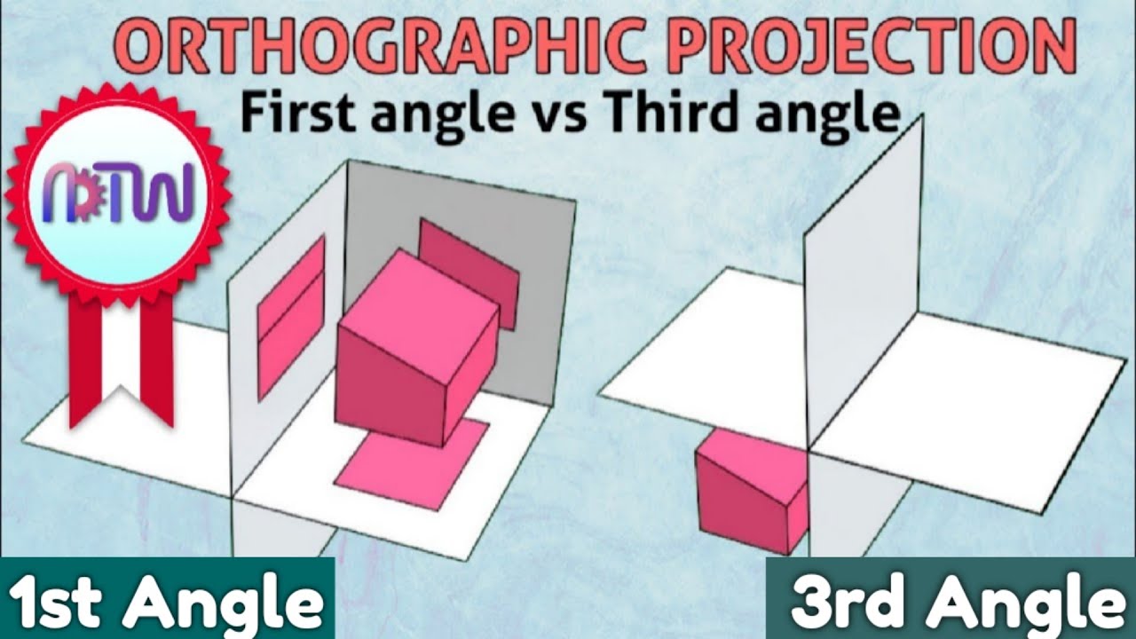
First angles vs Third angle method | Orthographic projections animation

Solid Geometry Grade 11
5.0 / 5 (0 votes)