54. Single Pulse-Width Modulation Technique
Summary
TLDRThis video explains the concept of Single Pulse Width Modulation (SPWM) to control the output of a single-phase full bridge inverter. It covers the working principle, where a triangular carrier signal is compared with a rectangular reference signal to generate base drive pulses for transistors in the inverter. The video explains how varying the amplitude of the reference signal controls the pulse width, influencing the inverter's output voltage. Additionally, it touches upon the mathematical calculations for the RMS output voltage and highlights the disadvantage of harmonic content, with a promise to address solutions in a future video.
Takeaways
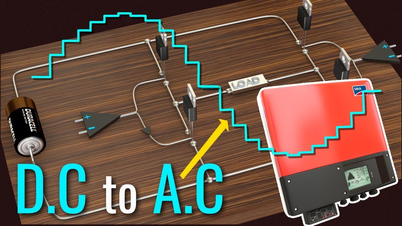
- 😀 The video discusses single pulse width modulation (SPWM) for controlling the output of a full bridge inverter in power electronics.
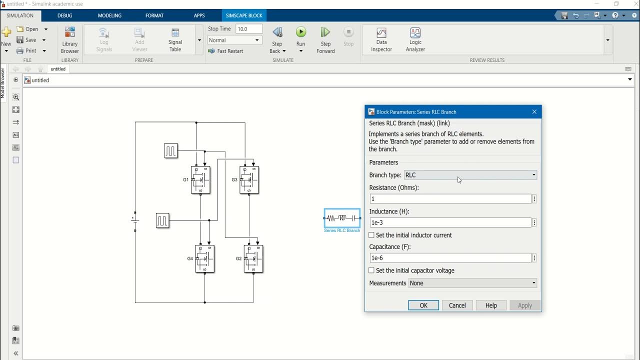
- 😀 The full bridge inverter operates with continuous output voltage, controlled by the base voltages of transistors, as shown in previous videos.
- 😀 Single pulse width modulation involves comparing a triangular carrier signal with a rectangular reference signal to generate base drive pulses.
- 😀 When the reference and carrier signals overlap, a base drive signal is generated for driving specific transistors (Q1, Q2, Q3, Q4) in the inverter circuit.
- 😀 The width of the base drive pulse (denoted as delta) is determined by the amplitude of the reference signal relative to the carrier signal.
- 😀 The modulation index is the ratio of the reference signal amplitude (Ar) to the carrier signal amplitude (Ac) and serves as a control variable.
- 😀 The output voltage waveform in SPWM has a single pulse per half cycle, which is the hallmark of the technique.
- 😀 The frequency of the output signal is determined by the frequency of the reference signal (Fr), and both the reference and carrier signals have the same frequency in SPWM.
- 😀 The mathematical formula for the rms output voltage in SPWM is derived based on the pulse width (delta) and is proportional to the square root of delta divided by pi.
- 😀 One major disadvantage of SPWM is the presence of harmonic content due to the single pulse per half cycle, which will be addressed in a future video.
Q & A
What is Single Pulse Width Modulation (SPWM)?
-Single Pulse Width Modulation (SPWM) is a technique where a triangular carrier signal with frequency Fc is compared with a rectangular reference signal with frequency Fr. When the two signals overlap, a pulse is generated that controls the base of the transistors in a full bridge inverter.
Why would we need to control the output voltage of a full bridge inverter?
-Controlling the output voltage of a full bridge inverter is necessary due to reasons like handling input DC voltage variations, controlling the output voltage, and meeting constant voltage or frequency control requirements.
How does SPWM help in controlling the inverter output voltage?
-SPWM controls the inverter output by varying the amplitude of the reference signal relative to the carrier signal. This change in amplitude affects the width of the base drive pulse, which in turn controls the output voltage.
What happens when the reference signal amplitude is zero?
-When the reference signal amplitude (Ar) is zero, the reference and carrier signals do not overlap, resulting in no base drive pulse being generated.
What is the modulation index in SPWM?
-The modulation index is the ratio of the reference signal amplitude (Ar) to the carrier signal amplitude (Ac). It acts as a control variable in SPWM.
How is the RMS output voltage calculated in the SPWM technique?
-The RMS output voltage is calculated as Vs multiplied by the square root of the ratio of delta (pulse width) to pi, where delta is the width of the pulse generated during each half cycle.
What is the frequency of the output signal in SPWM?
-In SPWM, the frequency of the output signal is determined by the frequency of the reference signal (Fr).
What are the base drive pulses in a full bridge inverter responsible for?
-The base drive pulses control the switching of the transistors in the full bridge inverter, ensuring the correct operation of the inverter circuit.
What is the impact of the single pulse per half cycle in SPWM?
-The single pulse per half cycle in SPWM can result in the generation of harmonic content, which is a disadvantage of this technique.
What can be done to overcome the disadvantage of harmonic content in SPWM?
-The disadvantage of harmonic content caused by the single pulse per half cycle can be addressed in future videos or techniques, as the speaker mentioned that a solution will be discussed in the next video.
Outlines

Cette section est réservée aux utilisateurs payants. Améliorez votre compte pour accéder à cette section.
Améliorer maintenantMindmap

Cette section est réservée aux utilisateurs payants. Améliorez votre compte pour accéder à cette section.
Améliorer maintenantKeywords

Cette section est réservée aux utilisateurs payants. Améliorez votre compte pour accéder à cette section.
Améliorer maintenantHighlights

Cette section est réservée aux utilisateurs payants. Améliorez votre compte pour accéder à cette section.
Améliorer maintenantTranscripts

Cette section est réservée aux utilisateurs payants. Améliorez votre compte pour accéder à cette section.
Améliorer maintenant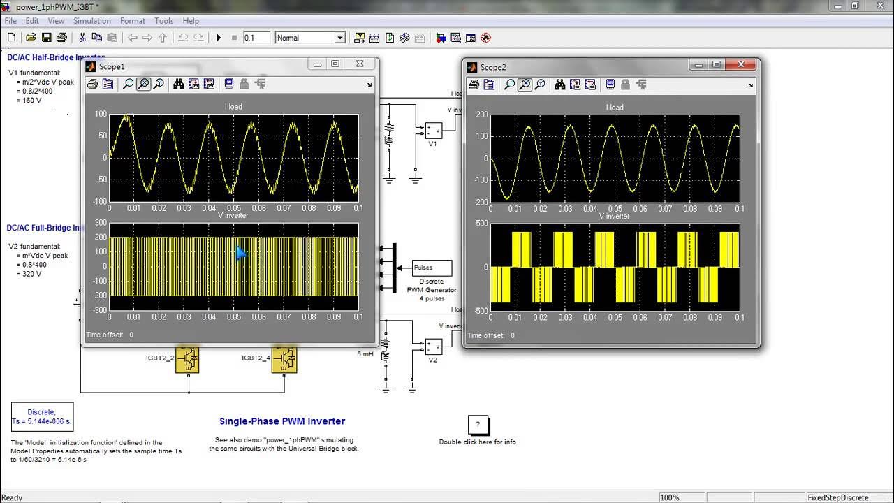


5.0 / 5 (0 votes)
