Inverter_simulink
Summary
TLDRIn this lecture, Prasetya discusses the simulation of half-wave and full-wave rectifier inverters using Matlab 2011. The focus is on Pulse Width Modulation (PWM) techniques for controlling AC signals, with a demonstration of single-phase inverters. The lecture covers the behavior of the rectifier inverters' output waveforms, including ripple characteristics and voltage regulation. It highlights the differences between half-bridge and full-bridge inverters, analyzing their respective Total Harmonic Distortion (THD) values. This session offers insights into inverter circuits, modulation techniques, and practical simulations for power electronics applications.
Takeaways
- 😀 The lecture focuses on simulating half-wave and full-wave rectifier inverters using Matlab 2011.
- 😀 The simulation uses Pulse Width Modulation (PWM) techniques to control AC signals with a modulation index of 0.8.
- 😀 The half-wave rectifier inverter uses a single leg, while the full-wave inverter uses a two-leg configuration.
- 😀 The fundamental voltage for a half-wave rectifier inverter is 160V, while for the full-wave inverter, it is 320V.
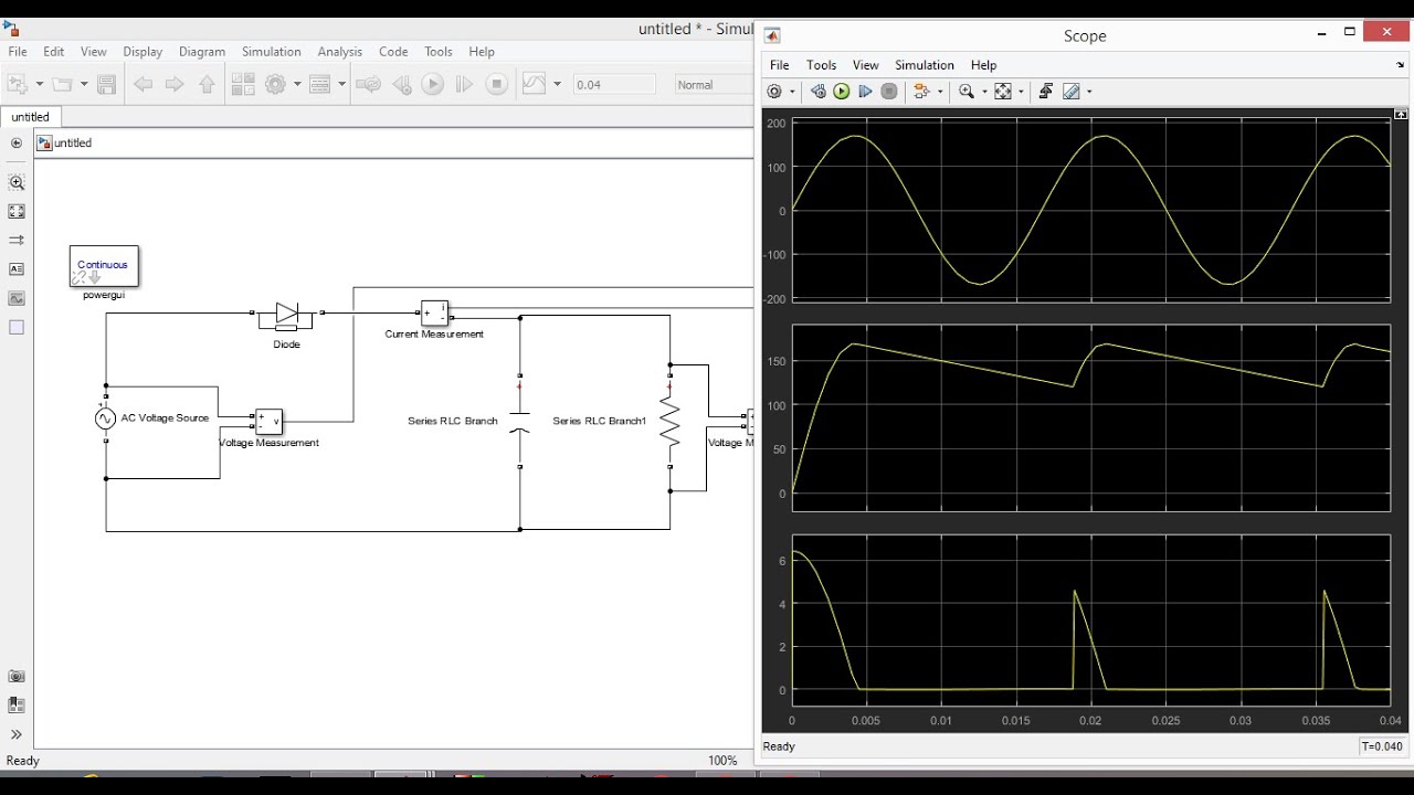
- 😀 The simulation compares the output currents and voltages of the two types of inverters using oscilloscope measurements.
- 😀 The output waveform for the half-wave inverter has a higher ripple, while the full-wave inverter produces a smoother output.
- 😀 The output of the inverters is controlled using a square wave signal for AC signal modulation.
- 😀 The half-wave inverter uses a single IGBT (Insulated Gate Bipolar Transistor) with parallel diodes, while the full-wave inverter uses two IGFTs and diodes.
- 😀 A Fast Fourier Transform (FFT) analysis is performed on the outputs to measure the Total Harmonic Distortion (THD).
- 😀 The THD for the half-wave inverter is 7.24%, while for the full-wave inverter, it is 2.01%, indicating smoother output for the full-wave inverter.
Q & A
What is the main focus of the lecture in the provided script?
-The main focus of the lecture is on simulating half-wave and full-wave rectifier inverters using MATLAB 2011. The lecturer discusses how Pulse Width Modulation (PWM) is applied to control the output voltage of inverters.
What role does Pulse Width Modulation (PWM) play in the inverter simulation?
-Pulse Width Modulation (PWM) is used to control the output voltage of the inverter. The modulation technique employed in the simulation adjusts the width of the pulses to regulate the AC signal output, enabling more efficient conversion and smoother waveform generation.
What types of inverters are discussed in the script, and what is the difference between them?
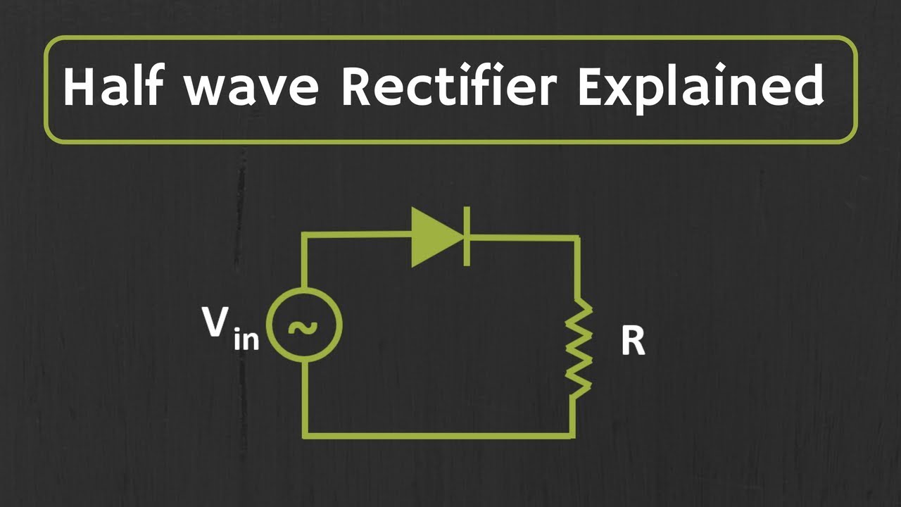
-The script discusses two types of inverters: half-wave rectifier inverter and full-wave rectifier inverter. The half-wave inverter uses a single leg of the circuit, whereas the full-bridge inverter uses two legs, providing a smoother output signal and lower ripple.
How is the frequency of the inverter output signal controlled?
-The frequency of the inverter output is controlled using a carrier frequency of 1080 Hz and a modulation index of 0.8. This influences the fundamental voltage of the output, which is critical for achieving the desired AC signal.
What is the significance of Total Harmonic Distortion (THD) in the inverter simulation?
-Total Harmonic Distortion (THD) is a measure of the deviation between the output waveform of the inverter and the ideal sine wave. A lower THD value indicates a smoother and more accurate AC output, while a higher THD indicates more distortion and a less clean output.
What are the key differences in the output between the half-wave and full-wave rectifier inverters?
-The key differences are that the half-wave inverter has a higher ripple in the output, resulting in a less smooth waveform, whereas the full-wave inverter provides a smoother output with lower ripple and a more accurate sine wave.
What are the components used in the inverter circuits discussed in the script?
-The inverter circuits discussed use IGBTs (Insulated Gate Bipolar Transistors), diodes, and switches arranged in parallel for the half-wave inverter. The full-bridge inverter uses two legs of IGBTs and diodes to create a full-wave output.
How is the output current from the inverter measured and analyzed in the simulation?
-The output current is measured using the Scope block in MATLAB. The current waveform is then analyzed using tools like the Fast Fourier Transform (FFT) to compute the Total Harmonic Distortion (THD) and evaluate the quality of the output signal.
What is the purpose of using a sampling time in the simulation?
-Sampling time is used to define the interval at which the signal is sampled during the simulation. This helps in analyzing the signal's performance, particularly for computing THD and assessing the behavior of the inverter circuit over time.
Why is the full-bridge inverter preferred over the half-wave inverter in this simulation?
-The full-bridge inverter is preferred because it provides a smoother and more stable output, with lower ripple and better voltage control, resulting in a more accurate representation of an AC signal compared to the half-wave inverter.
Outlines

This section is available to paid users only. Please upgrade to access this part.
Upgrade NowMindmap

This section is available to paid users only. Please upgrade to access this part.
Upgrade NowKeywords

This section is available to paid users only. Please upgrade to access this part.
Upgrade NowHighlights

This section is available to paid users only. Please upgrade to access this part.
Upgrade NowTranscripts

This section is available to paid users only. Please upgrade to access this part.
Upgrade NowBrowse More Related Video

Half-Wave vs Full-Wave Rectifiers - Electronics Basics 19
Half Wave Unctrolled Rectifier with C filter Matlab Simulink
Half wave Rectifier Explained

Half Wave Rectifier | IEE | GXEST104 | KTU 2024 |

MODUL1 PENYEARAH 1PHASE (HALF WAVE DAN FULL WAVE) MENGGUNAKAN SIMULINK MATLAB

Penyearahan gelombang penuh 2 dioda
5.0 / 5 (0 votes)