Project IoT (Internet of Things) | Menyalakan Lampu Lewat Telegram
Summary
TLDRIn this tutorial, learn how to create a simple IoT project that lets you control a light remotely via Telegram. Using the Not-MC microcontroller with a WiFi module and a relay module, the project demonstrates how to turn a light on and off by sending messages from the Telegram app. The setup involves connecting the components, programming the microcontroller through Arduino IDE, and configuring a Telegram bot. This project is a great introduction to IoT, allowing you to control your home appliances from anywhere as long as you have internet access.
Takeaways
- 😀 The project involves creating a smart home system using the Ayo Tisna project to control a light via Telegram messages.
- 😀 The key components needed are the Not EMSI microcontroller, relay module, jumper cables, and a light bulb.
- 😀 The Not EMSI microcontroller includes a WiFi module (ESP8266) which makes it suitable for IoT projects.
- 😀 A relay module acts as an electronic switch that is controlled by electrical signals, similar to a light switch.
- 😀 Jumper cables are used to connect the components, such as the microcontroller and relay module.
- 😀 The setup involves connecting VCC from the relay module to a 5V source and the GND to the ground, along with other connections.
- 😀 You will need to program the Not EMSI using Arduino IDE, defining necessary pins and including libraries for communication.
- 😀 A Telegram bot is created to allow remote control of the relay via message commands like 'relay on' and 'relay off'.
- 😀 The code checks for connection status and receives messages from Telegram to control the relay.
- 😀 If the message received from Telegram is incorrect, an error message is sent back to the user.
- 😀 The setup is tested by sending commands via Telegram, and it works based on the WiFi network speed, affecting response times.
Q & A
What is the main objective of the project described in the video?
-The main objective is to create a project that allows you to control the power (turning lights on and off) using Telegram messages through a Wi-Fi module and a relay.
Which microcontroller is used in this project, and why is it suitable?
-The project uses the NodeMCU microcontroller, which includes an ESP8266 Wi-Fi module, making it ideal for IoT applications like this one where Wi-Fi connectivity is required.
What is the purpose of the relay module in this project?
-The relay module acts as an electronic switch that can turn the connected light on and off using electrical signals, which are triggered by messages sent via Telegram.
What materials are necessary to build this project?
-The materials required for this project include a NodeMCU microcontroller (with ESP8266), a relay module, jumper wires, and a lamp for testing the system.
How do you connect the relay module to the NodeMCU?
-You connect the VCC of the relay to 5V on the NodeMCU, the GND of the relay to GND on the NodeMCU, and the D1 pin on the NodeMCU to control the relay module.
What programming environment is used for coding the NodeMCU?
-The NodeMCU is programmed using the Arduino IDE, which allows you to write and upload code to the microcontroller.
How do you enable Wi-Fi connectivity in the project?
-Wi-Fi connectivity is enabled by specifying the network SSID and password in the code, which connects the NodeMCU to a Wi-Fi network.
What is the role of the Telegram bot in this project?
-The Telegram bot is used to send commands (such as 'relay on' or 'relay off') to the NodeMCU. The bot's token is required to connect the project to the Telegram API.
What happens if the message sent through Telegram is not recognized?
-If the message sent via Telegram is unrecognized or incorrect, the NodeMCU sends a response back to Telegram indicating that the command is invalid.
What are the key conditions for the system to work effectively?
-The system works effectively as long as the NodeMCU is connected to the internet, the Wi-Fi network is stable, and the Telegram bot is properly set up with the correct token.
Outlines

Cette section est réservée aux utilisateurs payants. Améliorez votre compte pour accéder à cette section.
Améliorer maintenantMindmap

Cette section est réservée aux utilisateurs payants. Améliorez votre compte pour accéder à cette section.
Améliorer maintenantKeywords

Cette section est réservée aux utilisateurs payants. Améliorez votre compte pour accéder à cette section.
Améliorer maintenantHighlights

Cette section est réservée aux utilisateurs payants. Améliorez votre compte pour accéder à cette section.
Améliorer maintenantTranscripts

Cette section est réservée aux utilisateurs payants. Améliorez votre compte pour accéder à cette section.
Améliorer maintenantVoir Plus de Vidéos Connexes
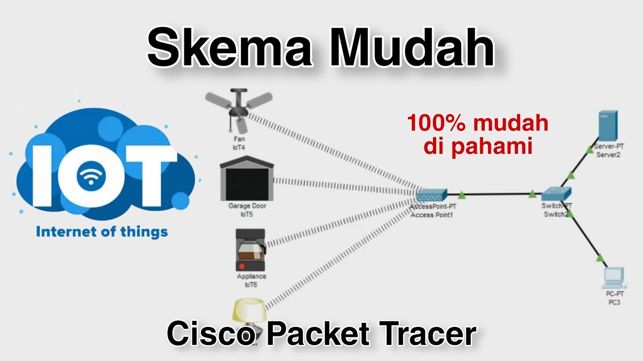
Konfigurasi IoT Perangkat Smart Home - Internet of Things | Cisco Packet Tracer
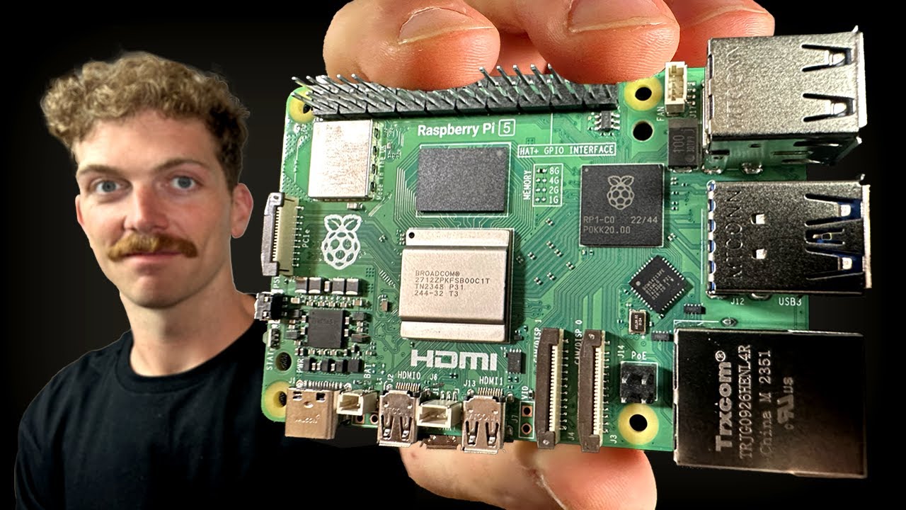
Every Developer Needs a Raspberry Pi

UTM - IoT Monitoring dan Kendali Menggunakan ThingSpeak dan Telegram

Control Water Pump From Mobile | IOT Projects | Home Automation
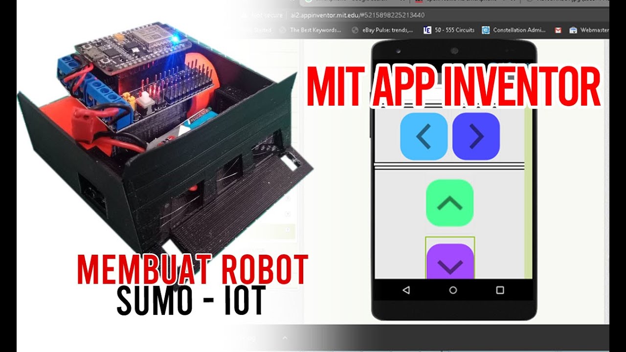
Membuat Robot SUMO IOT ESP8266 dan Aplikasi Android

Cara Remote Komputer dari HP dengan Chrome Remote Desktop
5.0 / 5 (0 votes)
