Part Modeling - Create Complex Hole Features
Summary
TLDRThis video focuses on a key objective from the Autodesk Fusion 360 Certified User exam: creating complex hole features in part modeling. The presenter demonstrates various methods to create and customize holes, including simple, counterbore, and countersink types. Techniques like using sketches, setting dimensions, and working with threading options are covered. The process is made clear with step-by-step instructions, including tips for editing features and checking the accuracy of hole placement. This video is aimed at helping users prepare for the Fusion 360 exam with practical examples and guidance.
Takeaways
- 🧩 The video focuses on an exam objective for Autodesk Fusion 360 certification, specifically creating complex hole features in part modeling.
- 📏 The tutorial begins by creating a simple block, which is a 6-inch by 2-inch rectangle, extruded to a depth of 1 inch.
- 📐 The first example demonstrates how to create a basic hole by adding a sketch point, setting constraints, and using the 'Hole' command.
- 🔧 Fusion 360 offers different hole types like simple, counterbore, and countersink, and these types are demonstrated throughout the video.
- 🔩 The video walks through adjusting hole parameters like depth, diameter, and taper angles to fit different design needs, starting with a simple hole.
- 🔍 A counterbore hole is demonstrated, showing how to use reference edges to position the hole at specific distances from the edges of the part.
- ⚙️ The tutorial explains the process for creating multiple holes using the same hole type, constraining them, and adjusting their dimensions.
- 🔨 A countersink hole with thread settings is demonstrated, showing how to adjust tap types, threading options, and drill point angles.
- 👁 The section analysis tool in Fusion 360 is introduced to review the internal structure of the holes and validate the hole creation.
- 💡 The tutorial emphasizes that users can modify hole features after creation by accessing the model history and editing the parameters.
Q & A
What is the main focus of the video?
-The main focus of the video is to demonstrate how to create complex hole features in Autodesk Fusion 360, which is one of the exam objectives for the Autodesk Certified User (ACU) exam.
What is the first step in creating a complex hole feature in Fusion 360?
-The first step is to create a new sketch on the front work plane and draw a rectangle that is 6 inches wide by 2 inches tall. This rectangle is then extruded to a depth of 1 inch to create a basic block.
How can you place a point on the block to start creating a hole?
-You can create a point by going to the 'Create' menu, selecting 'Point,' and then using the horizontal and vertical constraints to position the point at a specific location on the top face of the block.
What are some of the options available when creating a simple hole in Fusion 360?
-When creating a simple hole, you can adjust settings such as the depth, diameter, type (simple, counter bore, countersink), and drill point angle. You can also choose placement options like 'at a point' or 'from a sketch with multiple points.'
How do you create a counter bore hole in Fusion 360?
-To create a counter bore hole, you select the hole type as 'Counter Bore' in the hole command menu. You can adjust settings like the diameter and depth of the counter bore and choose to make the hole go all the way through the material.
What is the difference between a simple hole and a countersink hole?
-A simple hole is a basic drilled hole with no special features. A countersink hole has a conical recessed area at the top, designed for flathead screws or bolts, and can be threaded.
How can you create multiple holes at once in Fusion 360?
-You can create multiple holes by placing several points in a sketch, then selecting the 'Hole' command and clicking on the desired points. Each point can be used to define a different hole with specific settings.
What types of threads can you add to holes in Fusion 360?
-Fusion 360 allows you to add different thread types, such as simple, tapped, and tapered tapped. You can also define threading options like full thread and select from various sizes and classifications (e.g., coarse, fine).
What is the purpose of the section analysis tool in the context of creating holes?
-The section analysis tool allows you to view a cross-section of the model to see the internal features of the holes, such as threading, depth, and other characteristics. It helps verify that the hole has been created correctly.
How can you edit a hole feature after it has been created?
-To edit a hole feature, you can right-click on the hole in the model history tree and select 'Edit Feature.' This allows you to make changes to any specifications, such as diameter, depth, or type of hole.
Outlines

Cette section est réservée aux utilisateurs payants. Améliorez votre compte pour accéder à cette section.
Améliorer maintenantMindmap

Cette section est réservée aux utilisateurs payants. Améliorez votre compte pour accéder à cette section.
Améliorer maintenantKeywords

Cette section est réservée aux utilisateurs payants. Améliorez votre compte pour accéder à cette section.
Améliorer maintenantHighlights

Cette section est réservée aux utilisateurs payants. Améliorez votre compte pour accéder à cette section.
Améliorer maintenantTranscripts

Cette section est réservée aux utilisateurs payants. Améliorez votre compte pour accéder à cette section.
Améliorer maintenant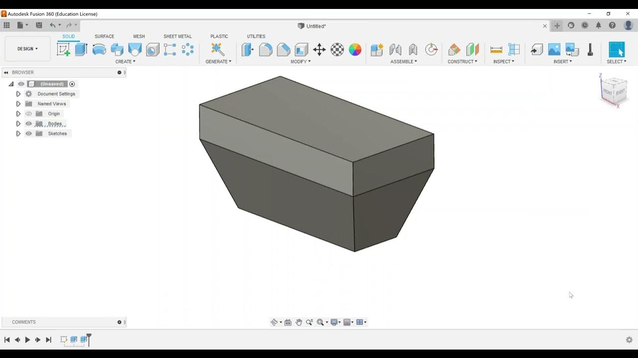


5.0 / 5 (0 votes)
