Working Principle of DC Motor (animation of elementary model)
Summary
TLDRThe script explains the working principle of a DC motor, highlighting its simplicity. It describes the basic construction, including the armature, commutator, and brushes, and the interaction with a magnetic field. The video uses Fleming's left-hand rule to demonstrate how current-carrying conductors experience mechanical force, leading to rotation. It illustrates the process with a model and concludes by emphasizing the continuous rotation due to the changing positions of conductors and the magnetic field's interaction.
Takeaways
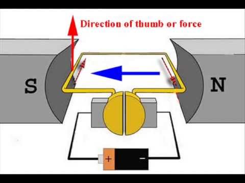
- 🔵 The working principle of a DC motor is based on the force experienced by a current-carrying conductor when placed in a magnetic field.
- 🔧 A basic DC motor consists of an armature, which is a current-carrying coil connected to a supply via a commutator and brushes, placed between the North and South poles of a magnet.
- 🔌 In a simple model, a single turn of a conductor is placed between two opposite poles, and when DC is supplied, the conductors experience a force due to the magnetic field.
- ➡️ Fleming's left-hand rule is used to determine the direction of the mechanical force acting on the conductors within the magnetic field.
- 🔃 The rotation of the armature produces a torque, causing the motor to rotate in a clockwise direction.
- 🔄 The commutator and brushes play a crucial role in reversing the current direction as the armature rotates, ensuring continuous rotation.
- 🔩 The motor's rotation continues due to inertia even when the current is momentarily interrupted as the brushes pass between commutator segments.
- 🔁 The process of current reversal and force application repeats as the armature continues to rotate, maintaining the motor's motion.
- 🏗️ In a more complex DC motor, multiple turns of wire are wound on a coil, and there are multiple poles instead of just two, enhancing the motor's efficiency and power.
- 📚 Understanding the working principle of a DC motor involves recognizing the interaction between electric current, magnetic fields, and mechanical motion.
Q & A
What is the basic principle behind the working of a DC motor?
-The basic principle behind the working of a DC motor is that when a current-carrying conductor is placed in a magnetic field, it experiences a mechanical force. This force can be determined using Fleming's left-hand rule.
What are the main components of a DC motor?
-The main components of a DC motor include a current-carrying armature, a commutator with segments, brushes, and a permanent or electromagnet with North and South poles.
How does the commutator play a role in the functioning of a DC motor?
-The commutator in a DC motor helps to periodically reverse the direction of current in the armature coils as the motor rotates. This ensures that the force on the armature is always in the same direction, causing continuous rotation.
What is Fleming's left-hand rule and how is it used in a DC motor?
-Fleming's left-hand rule is used to determine the direction of the force acting on a current-carrying conductor in a magnetic field. In a DC motor, it is applied to find the direction of mechanical force on the armature conductors, which helps in understanding the motor's rotation.
Why does the current direction in the armature change as the motor rotates?
-The current direction in the armature changes due to the action of the commutator as the motor rotates. This change ensures that the mechanical force on the armature continues to act in the same direction, allowing the motor to maintain its rotation.
What happens when the armature reaches a vertical position with respect to the magnetic field?
-When the armature reaches a vertical position with respect to the magnetic field, the conductors are aligned such that they are between the commutator segments, resulting in no current flow and thus no force acting on the conductors.
How does the motor continue to rotate after passing the vertical position?
-Due to the moment of inertia, the motor continues to rotate past the vertical position. As the armature moves into a horizontal position again, the commutator and brushes reestablish current flow in the conductors, which now experience force due to their new positions in the magnetic field.
What is the purpose of having multiple turns in the armature of a DC motor?
-Having multiple turns in the armature of a DC motor increases the total force and torque produced, which enhances the motor's ability to perform mechanical work.
How does the number of poles in a DC motor affect its performance?
-The number of poles in a DC motor influences the motor's speed and torque characteristics. More poles generally result in smoother and slower rotation, while fewer poles can lead to faster but potentially less smooth operation.
What is the role of brushes in a DC motor?
-Brushes in a DC motor make contact with the commutator segments to supply current to the armature coils. They play a crucial role in transferring electrical energy to the motor's rotating components.
Outlines

Cette section est réservée aux utilisateurs payants. Améliorez votre compte pour accéder à cette section.
Améliorer maintenantMindmap

Cette section est réservée aux utilisateurs payants. Améliorez votre compte pour accéder à cette section.
Améliorer maintenantKeywords

Cette section est réservée aux utilisateurs payants. Améliorez votre compte pour accéder à cette section.
Améliorer maintenantHighlights

Cette section est réservée aux utilisateurs payants. Améliorez votre compte pour accéder à cette section.
Améliorer maintenantTranscripts

Cette section est réservée aux utilisateurs payants. Améliorez votre compte pour accéder à cette section.
Améliorer maintenantVoir Plus de Vidéos Connexes
DC Motors: How Do They Work? Construction & Working Principle of a DC Motor | Electrical4U
3 point starter | 3 point starter dc motor | three point starter of dc motor | three point starter

EEE Project 2: GA Fuzzy PID controller for DC motor control

How does an electric motor work?

PID control of BLDC motor

Get Amped Up: The Science of Galvanometer Current Detection
5.0 / 5 (0 votes)
