Introduction to Diode: What is Diode ? V-I characteristics of the Diode Explained

ALL ABOUT ELECTRONICS
17 Jun 201815:47

Summary

TLDRThis video from the 'All About Electronics' YouTube channel introduces the concept of a diode, a two-terminal semiconductor device that allows current flow in one direction only. It explains the diode's V-I characteristics, distinguishing it from the linear behavior of resistors. The script delves into ideal and real diode models, including threshold voltage, forward and reverse biasing, and the importance of avoiding the breakdown region. It also touches on the significance of parameters found in diode datasheets, promising further exploration in subsequent videos.

Takeaways

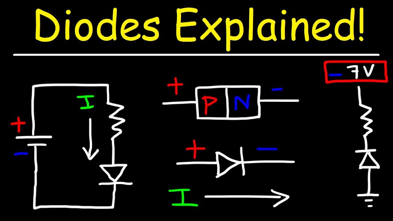
  • 🌟 The diode is a two-terminal semiconductor device that allows current to flow in only one direction.
  • 🔍 The symbol for a diode includes an arrow indicating the direction of current flow, with terminals named anode and cathode.
  • ⚡ The diode's operation is dependent on the polarity of the voltage applied between its terminals, allowing current only when the voltage is positive.
  • 📈 Diodes exhibit non-linear voltage-current (V-I) characteristics, unlike resistors which have a linear relationship.
  • 📊 The V-I graph of a diode can be misleading due to different scales on the positive and negative axes, but it fundamentally shows minimal current in the reverse direction.
  • 🔧 For circuit analysis involving diodes, the V-I characteristics are crucial for determining the voltage and current through the diode.
  • 🛠️ An ideal diode model simplifies analysis by acting as a closed switch under forward bias and an open switch under reverse bias.
  • 🔑 The V-I characteristics of an ideal diode are represented by a vertical line at the threshold voltage for forward bias and a horizontal line for reverse bias.
  • 🔄 Diodes have a threshold voltage, typically 0.6-0.7V for silicon and 0.3V for germanium, which is the minimum voltage needed to start conducting.
  • 🔍 The real behavior of a diode is approximated by considering it has a finite resistance (bulk resistance) after the threshold voltage is crossed.
  • ⚠️ Diodes should not be operated in the breakdown region, where excessive reverse voltage can damage the device, unless specifically designed for this purpose like Zener diodes.

Q & A

  • What is the main function of a diode?

    -A diode is a two-terminal semiconductor device that allows the flow of current in only one direction.

  • What are the two terminals of a diode called?

    -The two terminals of a diode are called the anode and the cathode.

  • How does the diode's directionality relate to the voltage polarity applied between its terminals?

    -The diode allows current flow when the voltage applied between the anode and cathode is positive, and it blocks current when the voltage is negative.

  • What is the difference between the V-I characteristics of a resistor and a diode?

    -A resistor has linear V-I characteristics, following Ohm's law, whereas a diode has non-linear V-I characteristics due to its unidirectional current flow.

  • What is the significance of the threshold voltage in a diode's operation?

    -The threshold voltage is the minimum voltage required to be applied across the diode for it to start conducting current in the forward direction.

  • What is the typical threshold voltage range for silicon and germanium diodes?

    -For silicon diodes, the threshold voltage is typically in the range of 0.6 to 0.7 volts, while for germanium diodes, it is usually around 0.3 volts.

  • How is an ideal diode represented in a circuit when forward-biased?

    -An ideal diode, when forward-biased, is represented as a closed switch in a circuit, allowing current to flow.

  • What is the reverse saturation current of a diode?

    -The reverse saturation current is the small current that flows through a diode in the reverse-biased region, typically in the micro-ampere range.

  • What is the breakdown region of a diode and why should it be avoided for normal signal diodes?

    -The breakdown region is when the reverse voltage applied to a diode exceeds a certain limit, causing a significant increase in current flow. It should be avoided for normal signal diodes as it can lead to diode damage.

  • What is a Zener diode and how does it differ from a normal signal diode?

    -A Zener diode is a type of diode specifically designed to operate in the breakdown region, allowing a controlled current flow when reverse-biased beyond its breakdown voltage, which is different from normal signal diodes that should avoid this region.

  • What is the role of bulk resistance in the second approximation of a diode's V-I characteristics?

    -In the second approximation, the bulk resistance represents the finite resistance offered by the diode after the threshold voltage is crossed, affecting the current flow through the diode.

  • Why is the diode resistance considered in the second approximation of the diode's behavior?

    -The diode resistance is considered to account for the actual behavior of the diode, which has a finite resistance that limits the current flow, especially when the Thevenin's equivalent resistance across the diode is comparable to the diode resistance.

Outlines

00:00

🔍 Introduction to Diodes

Welcome to the YouTube channel ALL ABOUT ELECTRONICS. In this series, we will cover various aspects of diodes, including their definition, V-I characteristics, equivalent circuits, and applications. A diode is a two-terminal semiconductor device that allows current to flow in only one direction, unlike a resistor which allows current in both directions. The diode's behavior depends on the polarity of the applied voltage, and its V-I characteristics are non-linear. The relationship between voltage and current in a diode is depicted by a graph which can appear symmetrical due to different scales on the axes. In reality, the diode blocks current in the reverse direction almost entirely.

05:01

🔧 Analyzing Circuits with Ideal Diodes

Using an example of a diode in series with a resistor and a voltage source, we analyze how the diode behaves as an ideal diode. When the applied voltage is positive, the diode acts as a closed switch, and current flows through the resistor. Conversely, if the applied voltage is negative, the diode acts as an open switch, preventing any current flow. The voltage across the diode can be found using Thevenin's equivalent method. The actual diode starts conducting only after the voltage exceeds a threshold value, known as the cut-in voltage. This approximation helps in finding more accurate values of voltage and current in the circuit.

10:03

⚙️ First Approximation of Diode Characteristics

In this approximation, the diode is considered ideal but will only conduct once the applied voltage crosses a threshold voltage. For a silicon diode, this threshold voltage is about 0.7V. When the voltage exceeds this value, the diode allows current to flow, acting as a closed switch. Below this threshold, it acts as an open switch. This model helps in understanding how diodes behave in real circuits and allows for more precise calculations of current and voltage.

15:07

📏 Second Approximation: Considering Diode Resistance

This approximation includes the diode's bulk resistance, which affects its V-I characteristics. Up to the threshold voltage, the diode offers infinite resistance, and after that, it offers a finite resistance determined by the slope of the V-I curve. This resistance, known as bulk or body resistance, is due to the semiconductor material of the diode. The equivalent circuit includes this resistance, providing a more accurate representation of the diode's behavior. The diode also has internal resistance due to its structure, which is significant in some circuits.

🔋 Real Diode Characteristics and Parameters

In real diodes, the V-I curve is piecewise linear. In the forward region, the diode conducts once the applied voltage exceeds the threshold, while in the reverse region, the current is minimal until breakdown. Diodes have parameters like maximum allowable forward current and reverse saturation current, which are crucial for their operation. The datasheet specifies these parameters, ensuring the diode operates within safe limits. Understanding these characteristics is vital for designing circuits with diodes and avoiding damage from excessive current or voltage.

📘 Conclusion and Further Learning

This video provided an overview of diodes, their V-I characteristics, and approximations for analyzing circuits. In the next video, we will delve deeper into diode resistance. Understanding these fundamentals is essential for working with diodes in various electronic applications. Viewers are encouraged to leave questions and suggestions in the comments and to subscribe for more informative videos on electronics.

Mindmap

Keywords

💡Diode

A diode is a two-terminal semiconductor device that allows current to flow primarily in one direction. It is a fundamental component in electronics, used for various functions including rectification, signal modulation, and voltage regulation. In the video, the diode is the central theme, with its behavior, characteristics, and applications being discussed in detail.

💡V-I Characteristics

V-I Characteristics, or Voltage-Current Characteristics, describe the relationship between the voltage across a device and the current flowing through it. For diodes, this relationship is non-linear and asymmetric, with the device conducting significantly more current when forward-biased than when reverse-biased. The script explains how these characteristics are used to analyze circuits containing diodes.

💡Equivalent Circuit

An equivalent circuit is a simplified representation of a more complex circuit that retains the same input-output relationship. In the context of the video, the equivalent circuit for a diode is discussed to simplify the analysis of circuits involving diodes, starting with an ideal diode model and then introducing more realistic elements like threshold voltage and series resistance.

💡Anode

The anode is the positive terminal of a diode. It is one of the two terminals that define the direction of current flow in a diode. The script mentions that the current direction is indicated by the symbol of the diode, with the arrow pointing towards the anode.

💡Cathode

The cathode is the negative terminal of a diode. It is the terminal from which conventional current exits the diode when it is forward-biased. The script explains that the polarity of the voltage applied between the anode and cathode determines whether the diode will conduct.

💡Forward Bias

Forward bias is a condition where the anode of a diode is at a higher potential than the cathode, allowing current to flow through the diode. The video script describes how a diode behaves under forward bias, including its V-I characteristics and the concept of threshold voltage.

💡Reverse Bias

Reverse bias is the opposite of forward bias, where the cathode is at a higher potential than the anode, causing the diode to resist current flow. The script explains that under reverse bias, the diode acts as an open switch, allowing only a small reverse saturation current to flow.

💡Threshold Voltage

Threshold voltage, also known as cut-in voltage, is the minimum voltage required to be applied to a diode to start conducting current in the forward direction. The script uses this term to describe the starting point of conduction in a diode, with specific values given for silicon and germanium diodes.

💡Breakdown Region

The breakdown region is a high voltage condition where a diode, typically not designed to operate in this state, begins to conduct a large current in the reverse direction. The script warns against operating diodes in this region and mentions that certain diodes like Zener diodes are designed to operate in the breakdown region for voltage regulation.

💡Bulk Resistance

Bulk resistance, also known as body resistance, is the internal resistance of a diode that limits the current flow once the diode is forward-biased and has crossed the threshold voltage. The script introduces this concept as part of the second approximation of a diode's behavior, providing a more realistic model of diode operation.

💡Datasheet

A datasheet is a document that provides detailed information about a component, including its electrical characteristics, operating conditions, and maximum ratings. The script mentions the datasheet as a source of parameters like maximum allowable forward current and breakdown voltage for diodes.

Highlights

Introduction to the diode as a two-terminal semiconductor device that allows current flow in one direction only.

Explanation of the diode's symbol, including the anode and cathode terminals and the direction of current flow indicated by the arrow.

Discussion on the polarity of the voltage applied to the diode and its effect on current flow.

Introduction to the V-I characteristics of a diode, emphasizing its non-linear relationship compared to a resistor.

Clarification of the diode's graph's symmetry and the different scales for positive and negative voltage and current.

Description of the ideal diode model and its V-I characteristics, acting as a closed switch for positive voltage and an open switch for negative voltage.

Illustration of how to analyze circuits with diodes using their V-I characteristics and Ohm's law for resistors.

Introduction to the concept of forward and reverse bias in diodes and their impact on current flow.

Example of a simple circuit with a diode, voltage source, and resistor, demonstrating current calculation with an ideal diode assumption.

Explanation of how to find the voltage across a diode using Thevenin's equivalent voltage.

Introduction of the threshold voltage or cut-in voltage as the minimum voltage required for a diode to start conducting.

Differentiation between silicon and germanium diodes in terms of their threshold voltages.

First approximation of the diode curve considering it as an ideal diode with a threshold voltage for conduction.

Second approximation including the diode's bulk resistance for a more accurate model of current flow.

Discussion on the diode's internal resistance and its impact on circuit analysis when comparable to other resistances in the circuit.

Description of the diode's operation in the forward region, including the exponential increase in current with voltage.

Warning about the breakdown region of diode operation and its avoidance for normal signal diodes.

Mention of Zener diodes designed to operate in the breakdown region, with further discussion planned for a separate video.

Summary of diode parameters found in datasheets, such as maximum allowable forward current and breakdown voltage.

Invitation for questions, suggestions, and engagement from the audience, encouraging subscription for more educational content.

Transcripts

play00:12

Hey friends, welcome to the YouTube channel ALL ABOUT ELECTRONICS.

play00:15

So, in this video and the subsequent videos, we will learn about the diode.

play00:20

And these are the following topics that we will cover in the series of videos.

play00:24

And in this particular video, we will learn that what is a diode, and how the V-I characteristics

play00:29

of the diode will look like.

play00:32

And we will also see the equivalent circuit for the diode.

play00:35

And in the subsequent videos, we will learn about the device physics of this diode and

play00:39

we will also see the different applications of the diode.

play00:41

So, now the question is what is a diode.

play00:44

Now, we all know about the resistor.

play00:46

It is the most widely used type of passive circuit element.

play00:50

And it allows the flow of current in both directions.

play00:52

Similarly, the diode is a two terminal semiconductor device which allows the flow of current only

play00:59

in one direction.

play01:00

And if you see the symbol of the diode, it looks like this.

play01:03

So, here this arrow indicates the direction in which this diode allows the flow of current.

play01:08

Now, the one terminal of this diode is known as the anode and the second terminal of the

play01:13

diode is known as the cathode.

play01:15

Now, whether this diode will allow the flow of current or not, it depends on the polarity

play01:20

of the voltage that is applied between this anode and cathode.

play01:22

So, if the voltage that is applied between this anode and cathode is positive, then,

play01:28

in general, we can say that this video will allow the flow of current in one direction.

play01:32

While the voltage that is applied between this anode and cathode is negative then it

play01:37

will not allow the flow of current.

play01:38

So, now when this diode connected in particular circuit and if we want to analyze that circuit,

play01:44

then the circuit can be analyzed by knowing the voltage and current that is flowing through

play01:48

this diode.

play01:50

And that can be found using the V-I characteristics of the diode.

play01:53

Now, for the resistor, we know that it is a linear element.

play01:56

And the relationship between the voltage and current is linear.

play01:59

So, using the Ohm's law, we can easily find the voltage and current through this resistor.

play02:05

But unlike the case of a resistor, the diode is a non-linear element.

play02:08

So, the relationship between the voltage and current for the diode is non-linear.

play02:13

And moreover that this diode allows the flow of current only in one direction.

play02:18

And it almost blocks the current in the reverse direction.

play02:21

Now, if you look at this graph, then it looks like, the graph is symmetrical in both directions.

play02:28

But don't get confused by the symmetricity, because here in this graph, both positive

play02:32

and the negative axis has a different scale.

play02:34

For example, on the positive Y-axis, we have a scale in milli-ampere.

play02:38

While on the negative Y- axis, we have a scale in micro-ampere.

play02:43

Similarly, on the positive X- axis if you see, the voltage varies like 0.5 V, 1V, and

play02:48

1.5V. While, if you observe on the negative X-axis,

play02:51

the voltage scale varies like -10V, -20V and -30V.

play02:57

So, because of the different scale, this characteristics looks symmetrical on both axis.

play03:03

But if we keep the same scale on both axis then the diode characteristics will look like

play03:07

this.

play03:08

So, as you can see, in the reverse direction the current that is flowing through the diode

play03:11

is almost negligible.

play03:12

So, using this V-I characteristic of the diode, we can easily find the voltage and current

play03:17

that is flowing through the diode.

play03:18

And using this we can easily analyze any circuit which contains this diode.

play03:23

But because of the non-linear characteristics of the diode curve, it is a bit difficult

play03:28

to find the voltage and current very easily.

play03:30

So, what we can do, we can approximate this diode characteristic and, using this we can

play03:35

analyze the circuits.

play03:36

So, first of all, what we will do, we will consider this diode as an ideal diode and

play03:41

for this ideal diode, we will see the V-I characteristics.

play03:44

And also we will see the equivalent circuit for this ideal diode.

play03:48

And step by step, we will introduce few more parameters to this ideal diode.

play03:53

And using this we will approximate the diode characteristic curve.

play03:57

So, for the ideal diode, whenever the voltage that is applied between the anode and cathode

play04:01

is positive, then simply it will act as a closed switch.

play04:06

On the other end, if the voltage that is applied between this anode and cathode is negative,

play04:10

in that case simply it will act as an open switch.

play04:13

So, now let's see the V-I characteristic for this ideal diode.

play04:16

So, in the case-1, when the applied voltage is positive, on the V-I characteristic we

play04:21

will get the vertical line.

play04:23

And for the case-2, when the applied voltage is negative then, for that case, we will get

play04:28

the horizontal line on the negative x-direction.

play04:31

So, this is the V-I characteristics for the ideal diode.

play04:34

So, now whenever the positive voltage is applied to this diode, then it can be said that the

play04:39

diode has been forward biased.

play04:41

And it will allow the flow of current.

play04:43

While on the other end, whenever the negative voltage is applied to this diode then it will

play04:47

not allow the flow of current.

play04:49

And simply we can say that it has been reversed biased.

play04:51

So, we will talk more about this forward and reverse bias at the later part of the video.

play04:56

So, now let's take one simple example, in which the diode is connected in series with

play05:01

voltage source and resistor.

play05:02

Now, here we are assuming that the diode is an ideal diode.

play05:06

It means that whenever the voltage that is appearing across the anode and cathode of

play05:10

the diode is positive then simply it can be represented by the close switch.

play05:15

And as you can see over here, the applied voltage across the diode is 10V.

play05:19

So, simply it can be represented by the close switch.

play05:23

And the current that is flowing through the100 ohm resistor will be equal to 10V divided

play05:27

by 100 ohms.

play05:28

That is equal to 0.1A. While on the other end, if we apply the -10V

play05:33

in this circuit, then the applied voltage across the diode will be -10V.

play05:38

And it will not allow any flow of current.

play05:40

So, simply it will act as an open switch.

play05:42

And the current that is flowing through the circuit will be equal to 0A.

play05:45

Now, some of you might have a question that how to find the voltage across this diode.

play05:51

So, that can be found by finding the Thevenin's equivalent between these two terminals.

play05:56

So, simply you need to remove this diode from the circuit and you need to find the Thevenin's

play06:00

equivalent voltage between these two terminals.

play06:02

So, if we remove this diode, then the Thevenin's equivalent voltage which appears between this

play06:07

anode and cathode in this particular case will be equal to -10V.

play06:11

And because of that, the diode will be nonconducting.

play06:15

On the other end, if 10V is appearing between these two terminals then diode will simply

play06:21

act as a closed switch.

play06:22

Now, if you see the V-I characteristics of this ideal diode, then you can observe that

play06:27

even if we apply very small positive voltage between this anode and cathode, then also

play06:32

this diode will start conducting.

play06:33

So, let's say, even if we apply positive 0.1 V, between this anode and cathode then also

play06:40

this ideal diode should start conducting.

play06:42

But if you see the actual diode, it will start conducting, only after applied voltage crosses

play06:47

some threshold voltage.

play06:49

And if you see the V-Characteristics, then it will look like this.

play06:52

So, up to certain threshold voltage, the diode will not allow any flow of current.

play06:56

And whenever the applied voltage crosses this threshold voltage, then only, the diode will

play07:00

allow the flow of current.

play07:01

So, this voltage is known as the threshold voltage or the Cut-in voltage for the diode.

play07:06

Now, like I said before, this diode is a semiconductor device.

play07:10

And usually, it is made of either silicon or germanium.

play07:14

So, for silicon, this threshold voltage used to be in the range of 0.6 to 0.7 V.

play07:19

While for germanium usually, it is around 0.3V.

play07:21

So, actually, the diode will start conducting once the applied voltage crosses this threshold

play07:27

voltage.

play07:28

And before that, it will not allow any flow of current.

play07:32

So, this is the first approximation for the diode curve.

play07:35

So, here in this approximation, we are considering this diode as an ideal diode but it will only

play07:41

allow the flow of current once the applied voltage crosses this threshold voltage.

play07:46

And the equivalent circuit will look like this.

play07:48

So, in case of reversed bias, it will simply act as an open switch.

play07:54

But whenever the applied voltage crosses this threshold voltage then only it will allow

play07:58

the flow of current.

play07:59

And simply it will act as a closed switch.

play08:02

so, now let's take the same example that we have taken earlier.

play08:06

So, in this approximation, we are considering this diode as an ideal diode except the fact

play08:12

that it will allow the flow of current only after that applied voltage crosses the threshold

play08:17

voltage.

play08:18

And here we are assuming that the diode that is used is the silicon diode.

play08:23

So, it has a threshold voltage of 0.7V.

play08:26

So, once the applied voltage crosses this 0.7V barrier, then only it will allow the

play08:31

flow of current.

play08:32

Now, here as the applied voltage is 10V, So simply this diode will allow the flow of current.

play08:39

And the equivalent circuit will look like this.

play08:41

So, now if you find the current that is flowing this 100-ohm resistor, it will be equal to

play08:46

10 V minus 0.7V divided by 100 ohms. that is equal to 0.093A.

play08:52

While on the earlier case, when we have considered this diode as an ideal diode, at that time,

play08:59

we found the value of this current as 0.1A. So, using this approximation, we can find

play09:05

the more accurate values of voltage and current int he circuit.

play09:08

Now, in the same approximation, suppose if we apply the -10V, then, in that case, the

play09:14

circuit will simply act as an open switch.

play09:17

And it will not allow any flow of current.

play09:19

So, the current that is flowing through this resistor will be equal to 0A.

play09:23

Now, in this first approximation also, we have considered that diode has zero resistance.

play09:30

And that can be also visible from the V-I characteristics of this diode.

play09:34

Because if you observe over here, once the applied voltage crosses this threshold voltage

play09:40

then the voltage that appears across the diode will remain constant.

play09:44

And current will increase.

play09:46

It means that the diode offers the zero resistance.

play09:49

But in the actual case, every device has some finite resistance.

play09:52

which will limit the current that is flowing through that particular device.

play09:56

Now, let's consider the second approximation, where we are also considering that the diode

play10:02

has some finite resistance.

play10:04

And in that case, if you see the V-I characteristics, then it will look like this.

play10:08

So, up to the threshold voltage, the diode will offer an infinite resistance, or simply

play10:13

it will act as an open switch.

play10:16

And then after it will provide some finite resistance.

play10:19

And that resistance can be found from the slope of this curve.

play10:23

So, this resistance is also known as the bulk resistance or the body resistance.

play10:27

So, this resistance is the resistance that is offered by the semiconductor device out

play10:32

of which this diode has been made.

play10:34

So, now let's see the equivalent circuit for this second approximation.

play10:38

So, whenever the diode is reversed biased in that case, simply it will offer the infinite

play10:45

resistance.

play10:46

Or we can say that it will act as an open switch.

play10:49

But whenever the applied voltage crosses this threshold voltage, in that case now it will

play10:54

offer some finite resistance of Rb.

play10:56

That is the bulk resistance of this diode.

play10:58

So, this is the equivalent circuit in case of the second approximation.

play11:03

Now, apart from this bulk resistance, the diode has one more resistance.

play11:09

And this resistance is present in the diode because of its internal structure.

play11:12

So, we will talk more about this diode resistance in the separate video.

play11:16

No, typically the value of this resistance used to be few ohms.

play11:20

So, in the circuit, if the Thevenin's equivalent resistance which appears across the diode

play11:25

is much more than the diode resistance, in that case, the diode resistance can be neglected.

play11:31

But if the Thevenin's equivalent resistance which appears across the diode is comparable

play11:36

to the diode resistance, in that case, we also need to consider this diode resistance.

play11:41

So, for example, in this case, let's assume that the diode has a resistance of 25 ohms.

play11:48

Now, this resistance is comparable to the 100-ohm resistor, so we need to consider this

play11:54

diode resistance.

play11:55

So, if we consider this diode resistance, then the current that is flowing through this

play12:00

100-ohm resistor will be equal to 10V minus 0.7V divided by 125 ohms.

play12:08

And if you see the current, it will be equal to 0.074A.

play12:12

So, because of this diode resistance, if you see, the actual current that is flowing through

play12:18

this 100-ohm resistor will change.

play12:20

So, using this second approximation, we can find the more accurate value of the current

play12:25

and voltage that is flowing through the circuit.

play12:28

But in most of the circuits, the Thevenin's equivalent resistance which appears across

play12:33

the diode used to be much larger than this diode resistance.

play12:37

And simply we can neglect this diode resistance.

play12:40

So, in this second approximation of this diode, we have assumed that the diode is non-conducting

play12:46

till the point this applied voltage crosses the threshold voltage.

play12:51

And then after it offers some finite resistance.

play12:54

So, if you see this type of characteristics then it is known as the piecewise linear characteristics.

play13:00

Because what we have done, we have segmented the actual characteristics of this diode into

play13:05

the piecewise linear characteristics.

play13:06

So, up to the threshold voltage, we have assumed that the diode is non-conducting.

play13:13

And after the threshold voltage, it will offer some finite resistance.

play13:16

OK, so now let's talk about the actual curve of this diode.

play13:21

So, in this diode curve, as I said before, this region is known as the forward region.

play13:26

Because, once the applied voltage crosses the threshold voltage, then the diode starts

play13:31

conducting.

play13:32

And whenever the applied voltage is less than the threshold voltage, in that case, the current

play13:37

that is flowing through the diode is almost negligible.

play13:39

So, now whenever we apply the reverse voltage to this diode, then that region of operation

play13:45

is known as the reverse region of operation.

play13:48

And in this region, the current that is flowing through the diode used to be very small, typically

play13:53

in the micro-amperes.

play13:55

And this current is known as the reverse saturation current of the diode.

play13:59

So, as you can see from the graph, even if we increase this reverse voltage across the

play14:04

diode, then also the current will only increase by a marginal amount.

play14:09

But we cannot increase this reverse voltage indefinitely.

play14:13

Because if we go beyond certain voltage then the diode will come into the breakdown region.

play14:19

So, this region of operation is known as the breakdown region and this region of operation

play14:24

should be avoided.

play14:25

Now, some diodes are specifically made to operate in this particular breakdown region.

play14:31

And this types of diodes are known as the Zener diode.

play14:34

So, we will talk more about this Zener diode in the separate video.

play14:39

But for any normal signal diodes, this region of operation should be avoided.

play14:44

So, if you see the datasheet, you will find that the maximum breakdown voltage for the

play14:50

diode has been mentioned.

play14:51

So, the applied reverse voltage should be less than this breakdown voltage.

play14:56

Now, in the forward region of this diode characteristic curve, if you observe, as the voltage across

play15:01

the diode increases, the current that is flowing through the diode will increase exponentially.

play15:06

Si, in datasheets you will also find the one more parameter that is known as the maximum

play15:12

allowable forward current.

play15:14

So the diode current should be less than this maximum allowable forward current.

play15:18

So, here are the few parameters that you will find in the datasheet of any diode.

play15:23

So, now in the next video, we will talk more about the diode resistance.

play15:27

So, I hope in this video, you understood what is a diode, and the V-I characteristics of

play15:32

the diode.

play15:33

So, if you have any question or suggestion then do let me know in the comment section

play15:37

below.

play15:38

If you like this video, hit the like button and subscribe to the channel for more such

play15:39

videos.

Rate This

5.0 / 5 (0 votes)

Etiquetas Relacionadas
ElectronicsDiodesV-I CharacteristicsCircuit AnalysisSemiconductorsDevice PhysicsResistor ComparisonCurrent FlowThreshold VoltageZener Diode
¿Necesitas un resumen en inglés?