Percobaan Pengukuran Tegangan Listrik Dengan Osiloskop | Praktikum Fisika Dasar 2
Summary
TLDRThis video provides a step-by-step guide to measuring electrical voltage using an oscilloscope. It explains how to set up the oscilloscope, calibrate it, and measure both DC and AC voltages using multimeters and oscilloscopes. The process includes connecting the voltage source to the devices, observing voltage readings on the oscilloscope, and comparing them to the multimeter values. The video also explains how to interpret the oscilloscope’s vertical and horizontal readings for accurate voltage measurement. The overall aim is to help users understand and apply the oscilloscope in electrical measurements effectively.
Takeaways
- 😀 The experiment aims to teach how to use an oscilloscope to measure voltage signals, including both AC and DC voltages.
- 😀 The oscilloscope allows users to observe the voltage signal's waveform over time, with applications ranging from industrial labs to hospitals.
- 😀 The experiment requires using tools such as an oscilloscope, AC/DC voltage sources, a multimeter, and connecting cables.
- 😀 To start, power on the oscilloscope and wait for the display to show up, then connect the probe to the channel you want to use.
- 😀 Calibration is important: connect the probe to the calibration marker, press the 'autoset' button, and adjust vertical scale until the calibration matches the oscilloscope display.
- 😀 For measuring DC voltage, connect the DC voltage source to both the multimeter and the oscilloscope, set the power supply to 3V, and compare readings.
- 😀 The oscilloscope should be set to 'DC' coupling mode to properly measure DC voltage signals, with vertical scale readings shown on the display.
- 😀 The same procedure should be followed for DC voltages of 6V and 12V, ensuring accurate measurements using both the oscilloscope and multimeter.
- 😀 For measuring AC voltage, switch the oscilloscope to 'AC' coupling mode, and follow similar procedures as for DC voltage measurements.
- 😀 The process of measuring AC voltage should be done for both 6V and 12V values, comparing results from the oscilloscope and multimeter for accuracy.
Q & A
What is the main objective of the experiment described in the video?
-The main objective of the experiment is to enable students to use an oscilloscope to measure the voltage amplitude and waveform, understand AC and DC voltage measurement techniques, and analyze electrical voltage signals accurately.
What is the purpose of calibrating the oscilloscope before starting the measurements?
-Calibrating the oscilloscope ensures that the readings are accurate and consistent. The process involves checking the vertical scale on the screen to match the calibration values provided, ensuring correct measurements during the experiment.
What tools and materials are required for the experiment?
-The required tools and materials include an oscilloscope, AC and DC voltage sources, a multimeter, and connecting cables.
How do you calibrate the oscilloscope?
-To calibrate the oscilloscope, connect the probe to the calibration point, press 'autoset', and adjust the vertical scale on the screen to match the calibration values. Once the values align, the oscilloscope is calibrated.
What is the correct procedure for measuring DC voltage using both a multimeter and an oscilloscope?
-First, connect the DC voltage source to the multimeter and set the power supply to 3V, recording the reading. Then, connect the same source to the oscilloscope, switch to DC coupling mode, and observe the waveform on the oscilloscope screen. Measure the vertical voltage using the oscilloscope's grid.
How do you adjust the oscilloscope settings for measuring DC voltage?
-To measure DC voltage on the oscilloscope, press the 'Menu' button, select the DC coupling mode, and then adjust the power supply to the desired voltage, such as 3V. The oscilloscope will display the waveform based on the selected voltage.
What is the process for measuring AC voltage using both a multimeter and an oscilloscope?
-Start by connecting the AC voltage source to the multimeter and setting the power supply to 3V. Note the multimeter reading. Then, connect the AC source to the oscilloscope, change the oscilloscope coupling mode to AC, and observe the waveform on the screen. Measure the vertical voltage from the waveform.
Why is it important to compare multimeter readings with oscilloscope readings during the experiment?
-Comparing multimeter readings with oscilloscope readings helps verify the accuracy of the measurements, ensuring that both instruments are providing consistent data. It also enhances understanding of how each tool displays voltage values.
What is the significance of the vertical grid on the oscilloscope screen?
-The vertical grid on the oscilloscope screen helps in measuring the voltage amplitude. Each box on the vertical axis corresponds to a specific voltage value, such as 0.2V per division, making it easier to read and record accurate voltage levels.
How should the oscilloscope settings be adjusted for different voltage levels (e.g., 6V, 12V)?
-To measure different voltage levels such as 6V or 12V, adjust the power supply to the desired voltage, and observe the corresponding waveform on the oscilloscope. The vertical grid and the oscilloscope's measurement tools will allow you to measure the correct amplitude for each voltage level.
Outlines

Esta sección está disponible solo para usuarios con suscripción. Por favor, mejora tu plan para acceder a esta parte.
Mejorar ahoraMindmap

Esta sección está disponible solo para usuarios con suscripción. Por favor, mejora tu plan para acceder a esta parte.
Mejorar ahoraKeywords

Esta sección está disponible solo para usuarios con suscripción. Por favor, mejora tu plan para acceder a esta parte.
Mejorar ahoraHighlights

Esta sección está disponible solo para usuarios con suscripción. Por favor, mejora tu plan para acceder a esta parte.
Mejorar ahoraTranscripts

Esta sección está disponible solo para usuarios con suscripción. Por favor, mejora tu plan para acceder a esta parte.
Mejorar ahoraVer Más Videos Relacionados
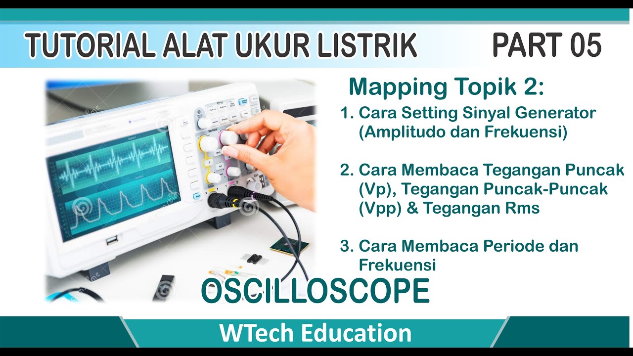
Membaca Tegangan dan Frekuensi Sinyal Generator dengan Oscilloscope
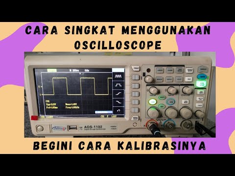
Belajar Cara Menggunakan Oscilloscope Digital | Cara Kalibrasi Oscilloscope Digital

Switch Mode Power Supply || SMPS Practical Demo|| Explanation and working || Power Electronics

Digital Multimeter | AC/DC Voltage Test | Multimeter Guide
Petunjuk Penggunaan Osiloskop Analog

Electronic Basics #1: The Multimeter
5.0 / 5 (0 votes)
