Petunjuk Penggunaan Osiloskop Analog
Summary
TLDRThis script provides a detailed guide on calibrating an oscilloscope. It covers step-by-step instructions for internal calibration, adjusting settings like channel activation, time and voltage scales, and triggering for stable signal display. It also explains how to measure signal parameters such as voltage, frequency, and delay, using various functions like cursors for precise measurements. The process includes troubleshooting tips for clear signal observation and accurate readings, ensuring proper alignment of the oscilloscope for various types of signal testing, including AC and DC measurements.
Takeaways
- 😀 Power on the oscilloscope by pressing the power button and ensure only the desired channel (e.g., channel 1) is active for calibration.
- 😀 Calibrate the oscilloscope by adjusting the horizontal and vertical position knobs to align the signal properly with the X-axis on the screen.
- 😀 Set the oscilloscope to AC mode by pressing the ACDC button and adjust the time and vertical scale for better signal clarity if needed.
- 😀 Use the BNC connector to link the oscilloscope to the signal source for calibration, ensuring the probe attenuation is set to x1.
- 😀 Adjust the scale settings for time and vertical alignment if the displayed signal is not clear enough for observation.
- 😀 If the signal is not steady, trigger the oscilloscope by setting the mode to auto and adjusting the trigger level to stabilize the waveform.
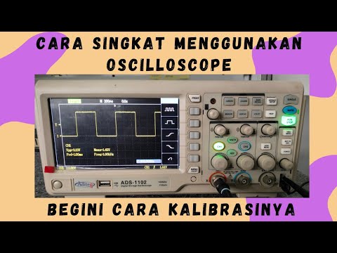
- 😀 Verify the calibration by checking if the displayed waveform matches the expected 0.5V peak signal with a frequency of 1 kHz.
- 😀 Switch to DC mode after calibration and ensure the oscilloscope's display aligns with the desired signal measurement, adjusting the knobs as needed.
- 😀 Use the ground button to ensure the zero level of the signal aligns with the X-axis, adjusting the position if necessary.
- 😀 For dual-channel measurements, activate X-Y mode, adjust both channel zero levels, and verify accurate delay measurements between the input and output signals.
Q & A
What is the primary function of an oscilloscope?
-An oscilloscope is a device used to measure voltage and frequency of signals displayed on a screen.
What is the internal calibration signal used for in the oscilloscope?
-The internal calibration signal is a square wave with a fixed voltage of 0.5 volts and a frequency of 1 kHz, used to ensure the oscilloscope's calibration.
How do you start the calibration process on the oscilloscope?
-To begin the calibration process, turn on the oscilloscope by pressing the power button, and ensure only the channel you want to calibrate is active.
What should you do if multiple channels are activated on the oscilloscope?
-If multiple channels are activated, turn off other channels by pressing the respective button (e.g., Channel 2) to avoid interference with the calibration process.
How can you adjust the display to show a solid horizontal line for calibration?
-Adjust the 'Time Diff' knob to rotate clockwise until a solid horizontal line appears, and use the 'Vertical Position' knob to align the line with the X-axis.
What is the purpose of the ACDC button in the calibration process?
-The ACDC button is used to switch between AC and DC modes on the oscilloscope to display the appropriate signal type during calibration.
How do you ensure the signal is clearly visible on the oscilloscope?
-To improve signal clarity, adjust the scale knobs for the 'Voltage' and 'Time Diff' settings. If the signal is still unclear, use the trigger function.
What should be done if the oscilloscope displays an unstable or unclear signal?
-If the signal is unstable, adjust the trigger settings. Set the trigger mode to 'Auto', set the source to Channel 1, and adjust the trigger level until the signal stabilizes.
How can you verify the oscilloscope is still calibrated correctly?
-If the oscilloscope displays a square wave signal with 0.5V and 1 kHz frequency, it confirms that the device is still properly calibrated.
How can you measure the voltage and frequency of a signal using cursors?
-To measure the voltage, use the cursor buttons to activate the horizontal lines, adjust them to the signal's peak and valley, and observe the Delta V value. For frequency, use the cursors to set the vertical lines around one cycle and observe the Delta T value, which can then be used to calculate the frequency.
Outlines

This section is available to paid users only. Please upgrade to access this part.
Upgrade NowMindmap

This section is available to paid users only. Please upgrade to access this part.
Upgrade NowKeywords

This section is available to paid users only. Please upgrade to access this part.
Upgrade NowHighlights

This section is available to paid users only. Please upgrade to access this part.
Upgrade NowTranscripts

This section is available to paid users only. Please upgrade to access this part.
Upgrade NowBrowse More Related Video
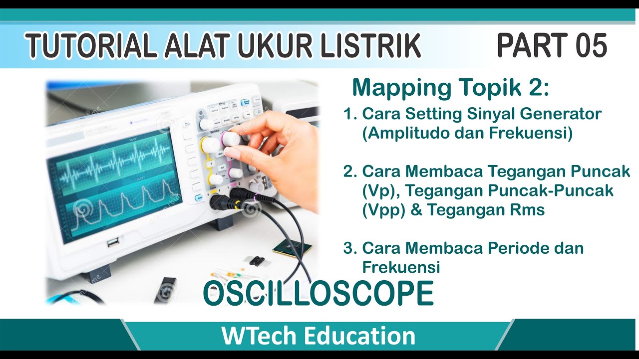
Membaca Tegangan dan Frekuensi Sinyal Generator dengan Oscilloscope

6a Praktek Cara Mengkalibrasi dan Menggunakan Osiloskop untuk Mengukur Tegangan dan Frekuensi
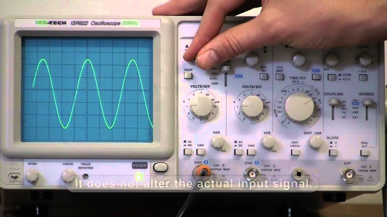
How to use an oscilloscope with an A/C source
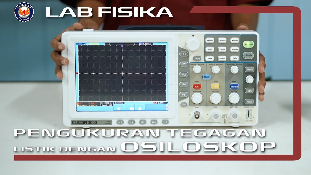
Percobaan Pengukuran Tegangan Listrik Dengan Osiloskop | Praktikum Fisika Dasar 2
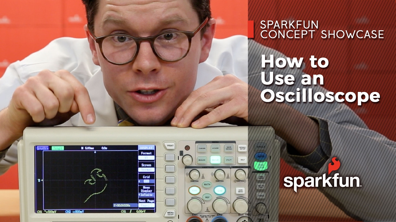
How to Use an Oscilloscope
Belajar Cara Menggunakan Oscilloscope Digital | Cara Kalibrasi Oscilloscope Digital
5.0 / 5 (0 votes)