Introducción a la robótica: Posición, orientación y tramas
Summary
TLDRThis video script delves into the fundamentals of robotics, focusing on the description of a point's position and orientation in space with respect to a coordinate system. The master explains the use of position vectors and rotation matrices to define a robot's arm orientation, emphasizing the importance of accurately representing both position and orientation. The concept of a 'transform', a set of four vectors encompassing position and orientation data, is introduced. The script also touches on the application of these principles in robotic arms, highlighting the kinematic chain's representation through coordinate systems and the practicality of using transforms for various robotic systems.
Takeaways
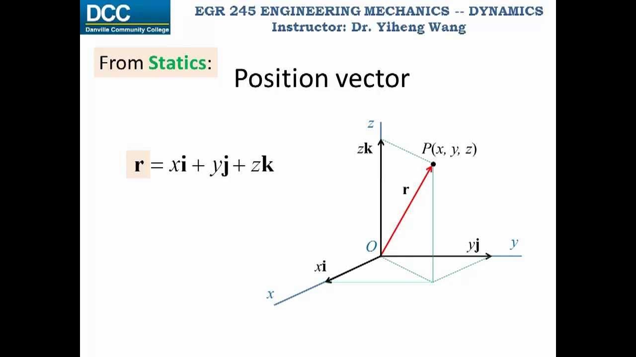
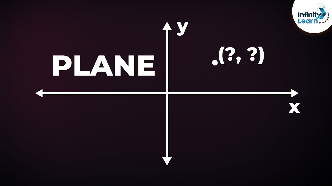
- 📍 The script introduces the concept of describing a point's position in space with reference to a coordinate system, specifically the A and Y coordinate system.
- 🔄 The point P can be represented by coordinates (x, y, z) in a right-handed coordinated system, with the superscript 'a' indicating reference to the A coordinate system.
- 🚦 The description of orientation is more complex than position and requires not one but three vectors to fully describe the orientation of a robotic arm or end effector.
- 📊 A 3x3 matrix, represented by 'R', is used to describe the orientation, which is essentially a rotation matrix from system A to system B.
- 🔢 The elements of the rotation matrix R are the projections of the principal vectors of system B onto the elements of system A, calculated using dot product and trigonometric functions.
- ⏬ The script explains that the rotation matrix R can also be represented as the transpose of matrix R, when analyzed by rows instead of columns.
- 🔍 By analyzing the rotation matrix by columns and rows, insights into the projections of the system B's vectors onto system A's vectors are gained.
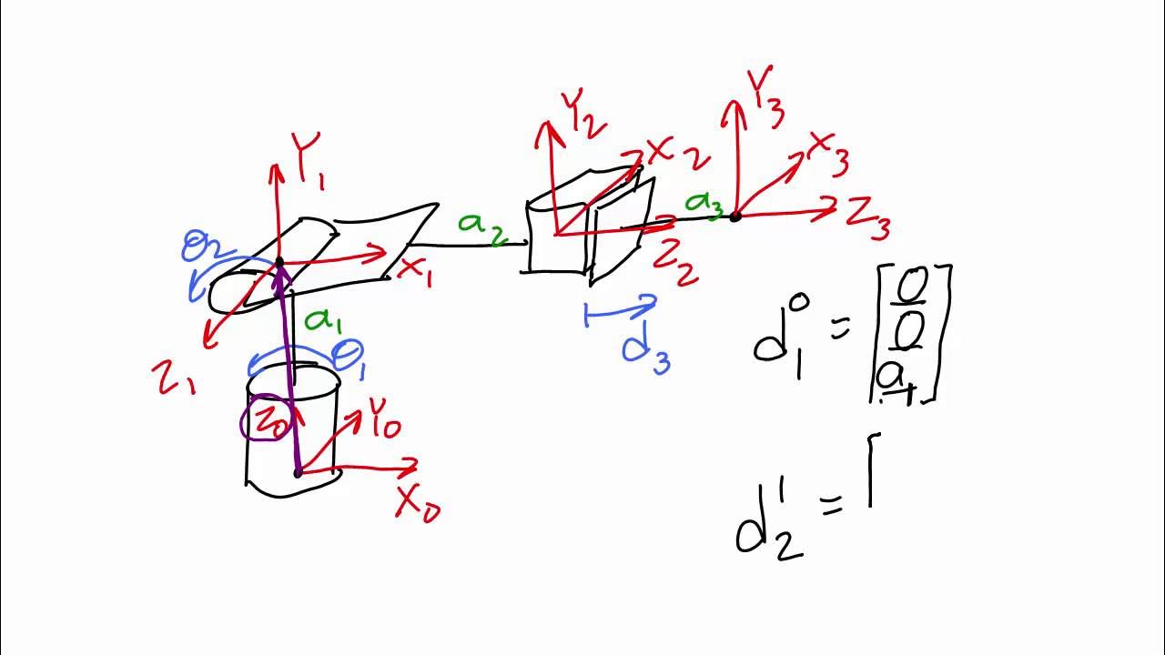
- 💠 The term 'transform' (trama in Spanish) is introduced as a set of four vectors providing information about position and orientation, consisting of a 3x3 rotation matrix and a position vector.
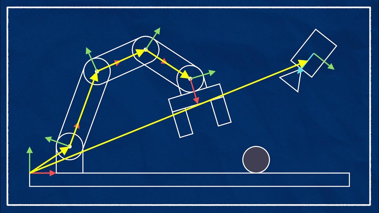
- 🔄 The transform allows representing any coordinate system relative to a previous or 'base' coordinate system, which is crucial in robotics for representing the kinematic chains of an articulated robotic arm.
- 📈 The script concludes by emphasizing the practical application of transforms in robotics, particularly in understanding the relationship between different coordinate systems in the context of a robotic arm.
Q & A
What is the main topic of the video?
-The main topic of the video is the description of the position and orientation of a point in space with reference to a coordinate system, specifically focusing on robotics.
How is a point represented in a coordinate system?
-A point is represented by its coordinates with respect to a given coordinate system. In the video, the point P is represented by its coordinates (x, y, z) in the A coordinate system.
What are the three axes of a right-handed coordinate system mentioned in the video?
-The three axes of a right-handed coordinate system mentioned are the x, y, and z axes.
Why is it necessary to describe the orientation in robotics?
-Describing the orientation is necessary in robotics because a robotic arm or end effector can be rotated in any direction while keeping a point stationary, and this rotation needs to be accounted for in addition to the position.
How many vectors are required to fully describe the orientation of a system?
-Three vectors are required to fully describe the orientation of a system, which together form a 3x3 matrix.
What does the 3x3 matrix represent in the context of the video?
-The 3x3 matrix represents a rotation matrix, which describes the orientation of one coordinate system (B) with respect to another (A). It is a mathematical representation of how the basis vectors of one system are projected onto the other system.
How is the rotation matrix (R) related to the transpose of the matrix?
-The rotation matrix (R) is the transpose of the matrix because when analyzed by rows instead of columns, it represents the projection of the basis vectors of one system onto the other, thus giving the orientation of one system with respect to the other.
What is a transformation matrix (or 'trama' in Spanish) in robotics?
-A transformation matrix, or 'trama', is a set of four vectors that provide information about both the position and orientation of a coordinate system. It consists of a 3x3 rotation matrix and a position vector.
How many coordinate systems can be represented in relation to the initial system?
-Multiple coordinate systems can be represented in relation to the initial system. Each subsequent system can be described with respect to the previous one, forming a chain of transformations.
What does the base system (system U) represent in the context of a robotic arm?
-In the context of a robotic arm, the base system (system U) represents the fixed part of the arm where the coordinate system origin is placed, and it is the reference point for the rest of the moving segments in the robotic chain.
How are the transformation matrices used in the kinematic chain of a robotic arm?
-Transformation matrices are used to represent the position and orientation of each link in the kinematic chain of a robotic arm with respect to the previous link. They help in calculating the overall position and orientation of the end effector.
Outlines
🤖 Introduction to Coordinate Systems and Robotic Arm Orientation
This paragraph introduces the concept of describing a point's position in space with respect to a coordinate system, specifically the A coordinate system. It explains how a point P can be represented by coordinates in the X, Y, and Z axes within a right-handed coordinate system. The paragraph further delves into the complexity of describing orientation, differentiating it from position. It highlights the need for not just one vector but three vectors (xv, yv, zv) to fully describe orientation, resulting in a 3x3 matrix. The explanation includes understanding the projection of the coordinate system's basis vectors onto each other and introduces the rotation matrix (R) as a representation of orientation, emphasizing its significance in robotics.
📐 Understanding the Spatial Representation of Coordinate Systems and Dexterity in Robotics
This paragraph continues the discussion on coordinate systems by explaining how the orientation of one coordinate system (B) is represented with respect to another (A). It describes the process of obtaining the orientation matrix (R) through vector projections and how this matrix can be transposed to represent the inverse relationship. The concept of a 'frame', a set of four vectors providing information about position and orientation, is introduced. The paragraph clarifies that the position is given by a vector (pdv), and the orientation is given by a 3x3 rotation matrix. It concludes by illustrating how multiple frames can be used within a robotic arm to represent the kinematic chain, with each frame's origin and vectors representing the links of the arm.
Mindmap
Keywords
💡Robotics
💡Coordinate System
💡Position
💡Orientation
💡Transformation Matrix
💡End Effector
💡Chain of Motion
💡Basis Vectors
💡Vector
💡Dot Product
💡Transposition
Highlights
Introduction to robotics and coordinate systems, specifically the A and B coordinate systems.
Description of a point's position in space with respect to a coordinate system.
Representation of point P in terms of coordinates with respect to the reference system.
Explanation of the orientation description being more complex than position description.
Requirement of three vectors, not one, to fully describe orientation.
Introduction of the 3x3 matrix representing the orientation of system V with respect to system A.
Clarification that the elements of the matrix represent the projection of the main vectors of the coordinate system.
Explanation of the dot product and its role in vector projection.
The notation R for the rotation matrix and its representation of the orientation of system V with respect to system A.
The transposition of matrix R to obtain the orientation of system A with respect to system B.
Description of the transformation matrix (frame) and its components: position and orientation.
The position vector (p_A) and its representation of the coordinates of the frame's origin.
Application of frames in robotics, particularly in the kinematic chains of an arm.
Use of the transformation matrix equation to represent the system with respect to a previous coordinate system.
The concept of a base or universal system and how other systems are represented with respect to it.
The practical application of the transformation matrix in the kinematic chain of a robotic arm.
Conclusion of the video and a teaser for the next topic.
Transcripts
hola que tal bienvenidos a un vídeo más
de robótica soy el maestro camacho y
comenzamos
en esta ocasión comenzaremos haciendo
algo que se llama descripción de la
posición de un punto en el espacio en
referencia a un sistema de coordenadas
dado en este caso el sistema de
coordenadas se llama a y tenemos los
tres ejes ordenados la x la y y la z en
un sistema coordinado derecho el punto p
se puede representar o se puede
describir en términos de la posición
mediante una coordenada o un punto en x
un punto en un punto en z como se
muestra en el vector columna de la
imagen el super índice a antes de la
letra p indica que todas las coordenadas
del punto p xp pz están dadas respecto
al sistema de referencia a la
descripción de la orientación no es tan
simple como la descripción de la
posición en la figura podemos observar
un brazo robótico o el efector final de
un brazo robótico el cual está ubicado
en el punto p esto quiere decir que las
coordenadas de dicho punto están
descritas mediante posición mediante
este vector p respecto al sistema de
origen o al sistema de coordenadas y
ahora para la orientación
resulta que nosotros podemos girar este
brazo robótico en cualquier orientación
o en cualquier dirección y que ese punto
ap se mantenga inmóvil es por eso que es
necesario describir la orientación
además de la posición para describir la
orientación de manera completa se
requiere no un vector sino tres vectores
que están aquí representados por x b hb
y aceptable
que nos resultan en un vector de 3 por 3
que serían 9 elementos en total donde
cada uno de estos elementos a xv ya se
está b representan la proyección de los
vectores principales del sistema de
coordenadas b que es el que está
adherido al efector final o al brazo de
la figura sobre cada uno de los
elementos que conforman al sistema
dígase x a jay-z
que es lo que observamos en esta otra
matriz de productos puntos ahora hay que
entender esta anotación de la r no se
llama r porque esto lo que en realidad
está representando es una matriz de
rotación que más adelante se va a
explicar del sistema ve al sistema o
dicho de otra manera es la
representación de la orientación del
sistema ve respecto al sistema y eso es
lo que significa esta anotación y
analizando cada uno de estos elementos
por columnas podemos observar con
claridad que la primera columna está
relacionada directamente con x debe que
ser primer elemento constitutivo del
sistema ve en producto punto con cada
uno de los elementos constitutivos del
sistema que sería x a jay-z lo mismo
ocurre en las otras dos columnas en el
caso de la segunda columna es la
proyección del segundo elemento
constitutivo del sistema b que sería la
y
en producto punto con los tres elementos
constitutivos del sistema a que sería la
x a jay-z y en la tercera columna ocurre
lo mismo pero con el tercer elemento
constitutivo del sistema b que sería el
vector zb entonces estos productos
puntos se están realizando porque de
esta manera es la forma matemática en la
cual representamos la proyección de un
vector sobre otro el cual pues se
resuelve mediante esta ecuación tenemos
una fórmula donde si tenemos el producto
punto de dos vectores vamos a poder
representarlo como la multiplicación de
sus valores escalares dígase la magnitud
de cada uno de estos vectores
por el coseno del ángulo que se genera
entre estos dos sectores entonces
recordando la anotación tenemos aquí que
la matriz r que representa a desde el
punto de vista de ve que si se dan
cuenta es lo inverso a lo que nosotros
aquí estamos indicando se puede
representar como la transposición de la
matriz r
dv respecto a esto porque ocurre porque
si nosotros analizamos esta matriz en
vez de por columnas en filas podemos
observar que la primera fila por ejemplo
es la proyección que hay del primer
elemento constitutivo del sistema que es
la x respecto a los tres vectores que
constituyen al sistema b que sería x y y
ceta eso en el caso de la primera fila
en la segunda fila tendríamos el mismo
caso nada más que respecto al segundo
elemento constitutivo del sistema que
sería la y
xb el punto y punto
y zp punto llegan y en la tercera fila
tenemos el mismo caso pero con el tercer
elemento constitutivo del sistema a que
sería la zeta entonces hago la
proyección de zeta respecto a la equis
en b la receta de a respecto a la que
debe y lo mismo en el tercero la z de a
re pero respecto a la z debe entonces si
lo observamos por filas básicamente si
nosotros trans ponemos esta matriz
obtendríamos precisamente la
orientación del sistema respecto al
sistema b que es lo que estamos viendo
escrito de este lado
en conjunto cuando tenemos la
representación de la posición y la
representación de la orientación de un
sistema de coordenadas obtenemos un
elemento que llamamos trama la trama es
un conjunto de cuatro vectores como dice
aquí que proporcionan información sobre
la posición y la orientación la
orientación está dada por la matriz de 3
x 3 que vimos en la diapositiva anterior
que sería una matriz de rotación del
sistema b respecto al sistema
y la posición la estamos dando mediante
un vector que estamos llamando aquí pdv
origen respecto a qué está aquí
representado en la figura que es
básicamente tres elementos x jay-z que
nos dicen cuáles son las coordenadas del
origen de la trama si tenemos estos dos
elementos podemos representar cualquier
sistema respecto a un origen oa un
sistema de coordenadas previas
en un brazo robótico tendremos múltiples
tramas siempre no vamos a tener
solamente una o dos como estamos viendo
en los ejemplos anteriores aquí en la
figura podemos observar un sistema que
les llamamos sistema universal o un
sistema base y tenemos un sistema un
sistema b y un sistema c cada uno de
estos sistemas tiene una representación
respecto a los demás pero en la realidad
lo que nos va a interesar es representar
los todos respecto al sistema inicial
que en este caso sería el sistema y
entonces yo creo que aquí se puede ir
entendiendo más fácil de qué manera se
utilizan estas tramas dentro del ámbito
de la robótica en el caso de que por
ejemplo el brazo robótico o la parte
fija de un brazo robótico normalmente es
donde se coloca el sistema o el sistema
de origen o el sistema universal y estos
vectores que son básicamente la posición
de origen del sistema en este caso el
sistema respecto al origen u
van a representar los eslabones de la
cadena cinemática de un brazo articular
entonces para el siguiente punto tenemos
precisamente el origen respecto al
sistema anterior que en este caso sería
el sistema por lo tanto aquí lo que
estamos viendo es que el sistema se
puede representar respecto al sistema y
el sistema se puede representar respecto
al sistema y de la misma manera del
sistema b se puede representar respecto
al sistema utilizando la ecuación de
tramas que hemos visto con anterioridad
eso sería todo por este vídeo y nos
vemos en el siguiente
Ver Más Videos Relacionados
Faster Freestyle Swimming: Part 2. Fingertip Orientation: High Elbow Catch | Vasa Swim Trainer
Position/Velocity/Acceleration Part 1: Definitions
Linear transformations and matrices | Chapter 3, Essence of linear algebra
Concave Mirrors Worked Example | Ray Tracing 2 of 5 | Geometric Optics | Doc Physics
What is a vector? - David Huynh
A&P I: chapter 1 orientation
5.0 / 5 (0 votes)