Op-Amp: Summing Amplifier (Inverting and Non-Inverting Summing Amplifiers)
Summary
TLDRThis video from the All About Electronics YouTube channel explains how to use an operational amplifier (op-amp) as a summing amplifier. It covers both inverting and non-inverting configurations, demonstrating how to add multiple input voltages and scale them using resistors. The video also explores practical applications like averaging input voltages, providing DC offsets, and mixing audio signals. It highlights the isolation of voltage sources in inverting amplifiers and the complexity involved with increasing inputs in non-inverting configurations, concluding with a preference for inverting summing amplifiers in practical scenarios.
Takeaways
- 😀 The video discusses the use of an op-amp as a summing amplifier, explaining how to add different input voltages using this configuration.
- 🔬 It covers both inverting and non-inverting op-amp configurations, detailing how multiple inputs can be applied to achieve summing.
- 🎚️ In the inverting summing amplifier, multiple inputs are applied to the inverting terminal, and the output voltage is expressed in terms of these inputs.
- ⚖️ The video assumes ideal op-amp conditions, where no current flows into the op-amp, and uses the concept of virtual ground to derive equations.
- 🔗 Kirchhoff's Current Law (KCL) is applied at node X to derive the relationship between input voltages and output voltage.
- 🔢 The output voltage for the inverting configuration is given by a formula that involves the feedback resistor and the input resistors.
- 📉 If all input resistors have the same value, the output voltage is the negative sum of the input voltages multiplied by the feedback resistor ratio.
- 🔄 The inverting summing amplifier can also perform scaling and averaging operations, adjusting the output based on the resistor ratios.
- 🎧 Practical applications of the inverting summing amplifier include adding, averaging, and scaling input voltages, as well as providing DC offsets and mixing audio signals.
- ⚠️ The number of inputs that can be practically added is limited by the power dissipation and the current supply capabilities of the op-amp.
- 🔀 The video highlights that in the inverting configuration, individual voltage sources are isolated due to the virtual ground concept, which is an advantage.
Q & A
What is the main topic of the video?
-The main topic of the video is the use of an operational amplifier (op-amp) as a summing amplifier, explaining how to add different input voltages using this configuration.
What is a summing amplifier?
-A summing amplifier is a type of electronic circuit that adds multiple input voltages together to produce a single output voltage.
How does the inverting summing amplifier configuration work?
-In the inverting summing amplifier configuration, multiple input voltages are applied to the inverting input terminal of the op-amp. The output voltage is the algebraic sum of the individual responses, scaled by the resistor values.
What is the significance of the virtual ground concept in the inverting summing amplifier?
-The virtual ground concept implies that the inverting input terminal of the op-amp is at ground potential due to negative feedback. This allows for the assumption that the voltage at this node is zero, simplifying the analysis of the circuit.
How does the non-inverting summing amplifier differ from the inverting one?
-In the non-inverting summing amplifier, input voltages are applied to the non-inverting input terminal. The output voltage is a function of the voltage at the non-inverting terminal, which is influenced by the input voltages and the resistor values.
What is the expression for the output voltage in an inverting summing amplifier?
-The output voltage in an inverting summing amplifier is given by Vout = -(Rf/R1 * V1 + Rf/R2 * V2 + Rf/R3 * V3), where Rf is the feedback resistor, and R1, R2, R3 are the input resistors.
What happens if all input resistors in an inverting summing amplifier have the same value?
-If all input resistors in an inverting summing amplifier have the same value, the output voltage Vout will be equal to -Rf/R * (V1 + V2 + V3), effectively summing the input voltages without scaling.
Can an op-amp be used to perform operations other than addition in a summing amplifier configuration?
-Yes, an op-amp can be used for scaling and averaging operations in addition to addition. It can also provide DC offsets to input signals, be used in digital to analog conversion, and mix different audio signals.
Why might the inverting summing amplifier be preferred over the non-inverting one in practical applications?
-The inverting summing amplifier is often preferred because it isolates individual voltage sources from each other due to the virtual ground, whereas in the non-inverting configuration, the sources influence each other.
How can the output voltage of an inverting summing amplifier be made positive?
-The output voltage of an inverting summing amplifier, which is inherently negative, can be made positive by connecting an additional inverting op-amp with unity gain.
What is the limitation of adding multiple input voltages in a summing amplifier?
-Theoretically, an unlimited number of inputs can be added, but practically, the number of inputs is limited by the power dissipation and the total current that the op-amp can supply.
Outlines

Esta sección está disponible solo para usuarios con suscripción. Por favor, mejora tu plan para acceder a esta parte.
Mejorar ahoraMindmap

Esta sección está disponible solo para usuarios con suscripción. Por favor, mejora tu plan para acceder a esta parte.
Mejorar ahoraKeywords

Esta sección está disponible solo para usuarios con suscripción. Por favor, mejora tu plan para acceder a esta parte.
Mejorar ahoraHighlights

Esta sección está disponible solo para usuarios con suscripción. Por favor, mejora tu plan para acceder a esta parte.
Mejorar ahoraTranscripts

Esta sección está disponible solo para usuarios con suscripción. Por favor, mejora tu plan para acceder a esta parte.
Mejorar ahoraVer Más Videos Relacionados
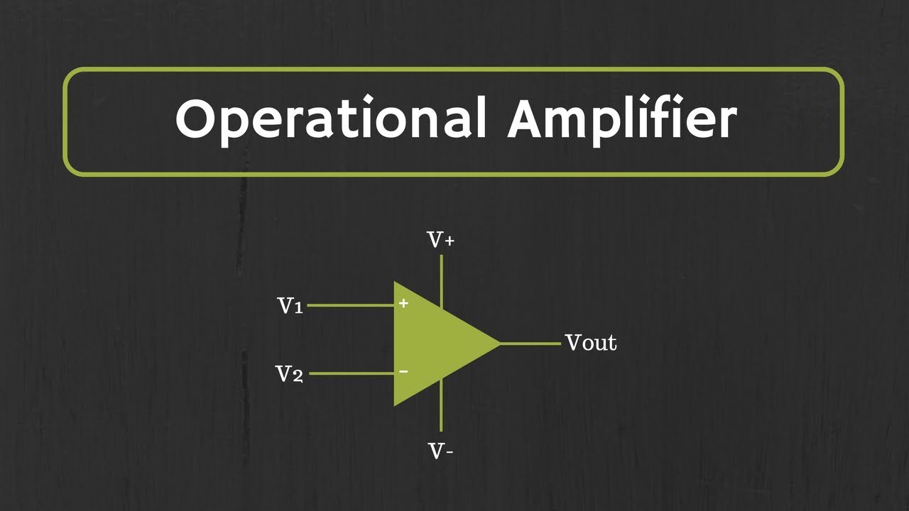
Introduction to Operational Amplifier: Characteristics of Ideal Op-Amp
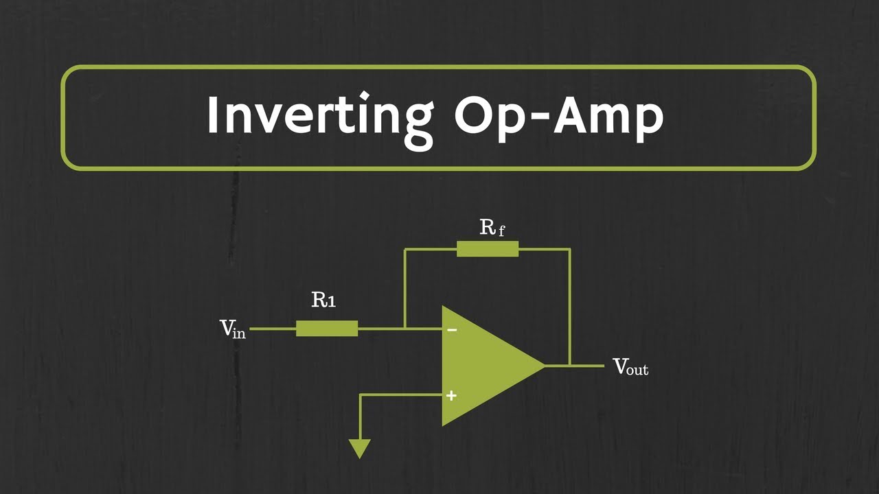
Operational Amplifier: Inverting Op Amp and The Concept of Virtual Ground in Op Amp
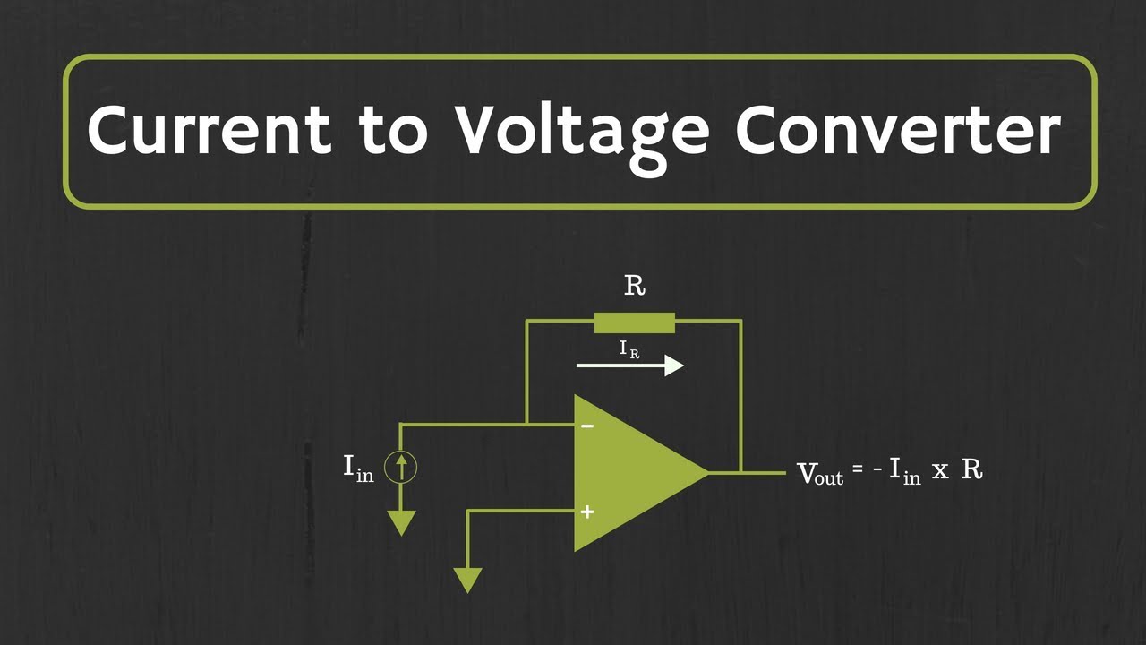
Op-Amp: Current to Voltage Converter (Transimpedance Amplifier) and it's applications

Operational Amplifier: Op-Amp as Differential Amplifier or Op-Amp as subtractor (With Examples)
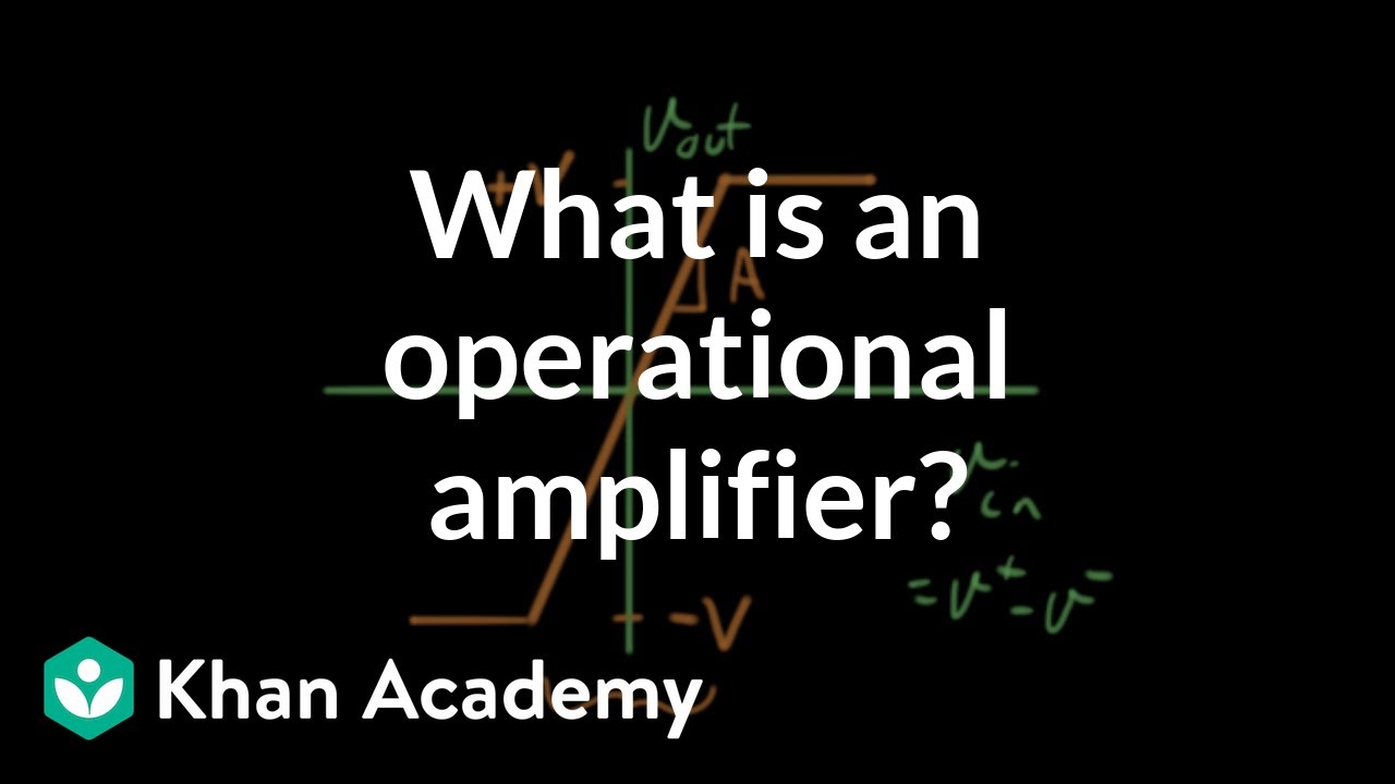
What is an operational amplifier?
MOSFET - Differential Amplifier (Small Signal Analysis)
5.0 / 5 (0 votes)
